Video coupling
There are three main modes of conveying an analogue video signal: com- posite video, S-video and RGB. We shall look at their characteristics in turn.
Composite video (CVBS) is the most common form of picture signal, representing the PAL (or other video signal) as broadcast by analogue terrestrial transmitters. While it can convey signals between any two pieces of video equipment it is mainly applicable to low-band VCRs and signals which come from analogue transmitters, satellite or terrestrial. The picture from a composite signal is limited in bandwidth/definition, and can dis- play cross-colour and other spurious effects.
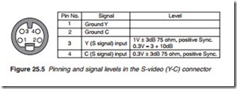
Similar to a composite video, the S-video coupling has separate leads and connections for luminance/sync and chroma components. It has the advantage of avoiding cross-talk effects like cross-colour, and it affords a little more picture definition by virtue of the absence of Y/C separating fil- ters. It is applicable to high-band (S-VHS, Hi-8) camcorders and VCRs, also digital TV receivers and DVD players where an S-output port is pro- vided. S-video is available in a specially designed plug/socket connector as shown in Figure 25.5. This cannot convey audio as well, so S-connection requires a separate audio link, typically in two (L, R) phono leads.
RGB offers the best possible video coupling mode for domestic appli- cations, but it is only applicable where the signal is generated on the spot, as it were: DVD players, DTV receivers. Here, there are separate paths for each primary colour: red, green and blue, with virtually no bandwidth restriction inherent in the linking system or mode. In home-video applica- tions, it is usually carried in SCART links as described above with sync at 300 mV peak on pin 20 (in) and pin 19 (out). VCRs do not deal in RGB sig- nals, though some models have a loop-through SCART facility for them.
Audio coupling
Sound signals are coupled between boxes at a standard level of 500 mV rms, most commonly in the SCART connector, but also in phono links, using sockets for both input and output with a colour code of red for right channel and white for left channel or mono: a yellow phono socket gener- ally carries video signals.
Dolby digital and other audio decoders and processors commonly form part of a home-cinema ensemble. Although they are concerned, for opera- tional purposes, solely with the sound signal, it is necessary to include them in the video path on its way to the TV or monitor so that their cap- tions and on-screen displays can be shown on screen. This enables the user to set up the system, check its mode and status, and get an indication of signal source. These processors/amplifiers are well equipped with input and output sockets for this purpose, and can form a convenient remote- controlled ‘switching centre’ for the various components of a complete AV system.
Speaker wiring
Apart from ensuring that each speaker is hooked to the correct socket— corresponding to its position in the room—the most important aspect of loudspeaker wiring is correct phasing, in which the + terminal of each speaker is connected to the + terminal on the box. Incorrect speaker phas- ing gives rise to strange and unnatural effects in the reproduced stereo or surround sound field. Loudspeaker power and impedance matching is also important: too ‘small’ a loudspeaker may get damaged at high vol- ume levels, while too low a loudspeaker impedance – for instance by con- necting two 4 Q units in parallel—risks damage, at high volume level, to the output section of the amplifier in the box.
Cordless loudspeakers and headphones save the need to run audio cables in the viewing/listening room. They depend on infra-red or RF transmitters at the box, whose emissions are picked up by mains and battery-operated receiver/demodulator/amplifier systems, respectively. The carrier frequency for IR types is 2.3/2.8 MHz, and for RF systems 863–864 MHz, with the latter generally giving the best results.
Digital ports
There are several digital connections in common use in domestic elec- tronic equipment. The digital video interface (DVI) and the high-definition multimedia interface (HDMI) were described in detail in Chapter 16. Some audio processor and video equipment such as digital TV receiver and DVD players are equipped to exchange multi-channel sound signals in digital bitstream format using optical fibre or RF/coaxial media. Here the com- plete audio bitstream is modulated onto an optical or RF carrier for lossless passage to a suitably equipped surround sound decoder.
