SERVICING POWER SUPPLY UNITS
The power-supply section of a TV or monitor vies with the line time- base section for the distinction of being the most troublesome area of operation, and as such the one most likely to need service attention when breakdown occurs.
The approach to servicing a faulty PSU depends very much on its design and vintage, and whether the fault is destructive of components. The first point to bear in mind is the safety aspect, especially where the chassis is not isolated from mains potential. In the workshop a double-wound isolating transformer is essential to reduce risk of electric shock to the technician. It should ideally be rated at 500 VA and protected on the secondary side by a 2.5 A anti- surge fuse; and on the primary side by a 5 A HRC fuse. While this will eliminate the risk of a mains-to-earth shock, it will not protect the operator if he completes a path between its secondary terminals or across any derived a.c. or d.c. voltages. This is particularly relevant where PSU ‘ground’ is at a different potential from signal ‘ground’ – in most designs the two are 320 V apart. PSU fault diagnosis is generally done with test instrument’s ‘low’ line connected to the common return line within the circuit – ‘PSU ground’, see, for instance, the top of Fig. 11.5.
Where the PSU is dead, normal voltage- and oscillogram-testing will trace the root of the fault; it is important to bear in mind the presence and effect of the various cut-out and trip circuits, however. A completely dead PSU may be the result of a short-circuit line output transistor, secondary rectifier or efficiency diode; so ohm- meter checks of such vulnerable components may solve the problem without an in-depth investigation of the PSU. If no overload is present, the lack of results will generally be due to failure of the switch-transistor or thyristor to turn on; the drive pulses can be checked back to source.
In cases where a trip circuit is obviously operating (indicated by a pulsing, ticking or initial burst of energy from the PSU) it is very unwise to disable the trip circuit itself – without protection, the fault currents and voltages can damage components. Much can be gleaned by carefully observing and evaluating the effects on each pump- cycle where relevant – the appearance of a burst of sound and expanding flash of picture, for instance, suggests that the timebases and PSU are working, but that the overvoltage trip is operating. In that particular case, monitoring the PSU output voltage with a d.c.- coupled oscilloscope (the response of a meter, analogue or digital, is too slow) will show it to rise slightly above normal on each pump- cycle, leading to an investigation of the PSU reference-voltage zener diode and the resistive network associated with the ‘set voltage’ preset control. Other ‘pump-cycle’ effects may be a squawk or arc from the l.o.p.t. (insulation breakdown or incorrect line frequency) or a low- frequency ‘thump’ with no activity in the timebase or audio stage (heavy loading on PSU-derived line; l.o.p.t. or tripler failure etc.).
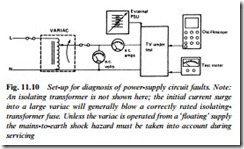
The most difficult PSU faults to deal with are those which cause damage to components – within or external to the PSU itself – at the moment of switch-on. Very often cold-checking of relevant semiconductors will reveal the culprit. If not, and where the cause of a trip coming into action is not obvious, an almost indispensible aid is a variac, a variable mains transformer. With this device, applied mains input voltage can be ‘wound up’ from zero while voltages and currents are monitored by test instruments. Where kick-start circuits are employed, especially those incorporating a charging capacitor, it will be necessary to override them by means of an external supply, or a suitable bypass resistor.
The application of an external voltage (i.e. from a low-voltage bat- tery or stabilised power supply unit) is a useful aid to diagnosis, applicable to both discrete and IC-based SMPSU control circuits.
With an appropriate operating voltage applied, the oscillator, control section and sometimes the driver stage can be made to run for study of drive waveforms and voltages. Since the chopper device is unpow- ered at this time there is no risk of damage; with correct drive established (and still in the presence of the low-voltage external sup- ply) the variac can be used to judiciously turn up the ‘mains’ voltage; the set-up for this is outlined in Fig. 11.10.
The capacitors used in SMPSUs work hard, and sometimes fail with various effects: trouble in the primary reservoir capacitors may cause heavy 100 Hz modulation of supply lines, with a moving wasp- waist travelling vertically over the picture; drying up of the second- ary (PSU output) reservoir capacitors may cause line-rate modulation of their supply line, leading to shading effects or operation of the over-volts trip on ripple-peaks. The same fault in PSU-internal capacitors used for smoothing the sampling voltage or the control- system operating voltage often gives rise to a tearing of the picture and/or a squawking noise from the chopper transformer. The latter effect is often dependent on tube beam-current, when it will vary with adjustment of brightness and contrast controls.
