CONTROL SYSTEMS
The increasing sophistication of TV and video equipment (reflected in earlier chapters of this book) and its interactive nature has necessitated the development of control systems which are largely automatic in operation. They devolve into three broad groups: user- control of equipment function; equipment-internal management of data and commands; and inter-equipment links, in which the operation of associated units is co-ordinated by ‘command’ links between them.
The most tangible and familiar of these is the cordless remote control handset by which much modern consumer entertainment equipment is ‘driven’. The serial data link takes the form of an infra- red (IR) transmission, in which the carrier is a beam of light whose wavelength is about 950 nm (frequency 316 000 GHz), which lies just below the visible spectrum. This very high carrier frequency permits the use of advanced modulation systems: the data is invariably transmitted in serial PCM form with the IR carrier turned fully on or off in a closely defined time sequence. As with all PCM systems, it is the pulse timing and nothing else which defines the command, and the use of check codes and filters – electrical and optical – gives great immunity to interference and misinterpretation of commands.
Internal data management has already been touched upon in the syscon arrangements described in Chapter 16. Various serial and parallel data bus formats are used within single equipments, their complexity depending on the features offered. Internal data systems are required to interface with RC receiver/decoders, and generally require access to ROM and manipulation of RAM; this is particularly relevant to FS tuning systems (Chapter 3), teletext and viewdata (Chapter 8) and deck control for both videorecorders (Chapter 16) and disc players (Chapter 20). For the latter some very sophisticated control systems are used in conjunction with a computer in interactive video applications.
Systems are also available to control signal-routeing and operating conditions in separate, but inter-linked equipments, and can be implemented by remote handset or even over the telephone. One such system will be described towards the end of this chapter.
IR REMOTE SENDER
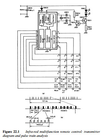
As can be seen from the circuit diagram of Fig. 22.1(a) the component count of a modern handset is very low, consisting here of twelve electrical components plus the battery and keyboard. The single IC is designed for minimal current consumption (<2 μA) in standby to conserve battery energy. The clock oscillator has no need of high precision or stability, and the cheap ceramic resonator con- nected between chip pins 11 and 12 provides an adequate frequency
reference around 450 kHz. When no button is depressed the oscillator is off. Pin 1 of the chip is low, transistor TB01 off and the transmitting LEDs DB01 and DB02 off.
When a key is pressed a current is detected within the IC and the oscillator starts. To prevent false operation due to key-bounce a 20 ms period is allowed before the key-detect process starts, when IC output pins 13–19 are strobed via a key-scan system (refer to Fig. 16.4 and associated text). A return pulse enters the chip on one of pins 5–8 and is decoded to identify the function requested. Even if the key is released at this point, the entire command word is generated and transmitted before the circuit returns to standby; if two or more keys are pressed simultaneously the commands are rejected.
Each key retrieves a specific command code from chip-internal ROM, and the required bit-sequence is made up by a processing section within the chip, driven by the clock. Remote control com- mands are pulse-position coded, each pulse consisting of a burst of 38 kHz carrier – this permits the use of a sharply tuned filter at the receiver for immunity from noise and interference. The spac- ing between pulses determines whether the pulse represents 0 or 1: a 7.59 ms period indicates a 1 and a 5.06 ms period a 0. A complete command consists of eleven bits: a reference bit, a toggle bit, three address bits and six bits for the actual command, as shown in Fig. 22.1(b).
The first bit is always 1, and is for use as a time reference in the decoder – its duration is measured, stored and used as a time base for the serial-to-parallel decoding process of the pulse-train which follows. The second (toggle) bit changes state each time a key is pressed, so that the decoder can discriminate between ‘new com- mand’ and ‘end of interruption in transmission’, e.g. someone walks through the light beam. The need for the toggle bit arises because the data transmission is continuous while any key remains pressed, in order to operate analogue functions like brightness and volume. On the other hand such functions as teletext page selection need sequential number keying, for which the toggle bit resets the decoder.
The next three bits are address bits which identify the sender and receiver/decoder, and act as a turnkey for the decoding of subsequent bits. In simple RC systems like this one a single address is used; here it is address 0, whose code (Fig. 22.1(b)) is 111. Finally comes the command itself in the form of a 6-bit code. Six bits offer 64 combina- tions, not all of which are used. The code 010001 is shown in the diagram, corresponding to ‘channel 6’ in this system: 001100 is brightness-up; 011110 will switch the set into standby, and so on. If any key is held down continuously, its command is repeated every 121 ms.
The pulse-coded output appears at pin 1 of the IC, and via RB02 switches output transistor TB01 between heavy conduction and cut- off. The sampling resistor RB01 and feedback transistor TB02 maintains peak LED current at around 1.3 A. The internal resistance of the small battery used is too great to supply this order of current, so large reservoir capacitor CB04 is essential. Because of the low duty-cycle of the pulse signal, however, the average battery current is only 14 mA during command transmission. Even at the rate of 1000 commands per day the battery life is many months. DB03 protects the IC from the effects of reversed connection of the battery. The circuit will operate over a wide range of battery voltage though imminent exhaustion is signalled by insensitivity.

