Interconnectivity and ports
As the count of electronic ‘black boxes’ in the home increases, so do the number and complexity of the connections between them. The evolution of technology has brought with it progressively better and lower-loss sig- nal linkages; over the years, we have moved from RF to composite video and then to S-video coupling for the picture and now use RGB links for some equipment. The advent of digital transmission and recording equip- ment, and the convergence of TV and computer technology and systems have spawned the domestic use of Firewire/IEE1394 data coupling. And increasingly we exchange control commands and data between boxes for the purposes of editing, automated recording, function switching and the like. This chapter examines the pros and cons of the various coupling and connection systems used in the domestic environment.
RF connections
For full versatility in recording and viewing of broadcast transmissions, the UHF aerial feed must be looped through the VCR and terrestrial DTV box on its way to the TV set. Some equipment (particularly satellite boxes) can generate interference in the UHF band, in which case the use of double-screened cable like the CT 100 type used for satellite downleads can be helpful when used for inter-equipment links working at UHF. Even though VCRs and terrestrial DTV receivers must have a UHF input, it is far better that their modulators are switched off, and that their signal out- puts go via AV (usually SCART) cables to avoid carrier clashes and conse- quent interference in the UHF band; these boxes are often designed to act as ‘switching centres’, automatically routing the AV signals as required.
Where a VCR and/or DTV box is required to feed several screens simultaneously, perhaps at widely different points, RF distribution can be used; if more than two TV sets are involved, a multi-output UHF ampli- fier will be necessary, and by this means many receivers can be fed, at great distances if required. This system does not permit stereo sound to be conveyed, and may involve difficulty in setting carrier frequencies to avoid interference, but has the advantage of simplicity and convenience. Figure 25.1 shows a local UHF network.
Very often a household distribution system involves the main TV in the lounge and a second set in bedroom or kitchen, from where it is required to ‘drive’ the equipment in the living room. It can be achieved by the use of a remote control extender which has an infra-red receiving eye near the
second TV to relay command codes—either via the RF cable or by a wire- less link—back to a mains-powered repeater in sight of the equipment to be controlled. Sky digital receivers have a built-in facility to power and operate a ‘Remote Eye’ which is simple to connect using just a coaxial cable, but whose operation is limited to the sat-box itself.
Baseband distribution
Better picture and sound quality in a ‘local network’ comes from using a baseband distribution system as shown in Figure 25.2. This also gives the opportunity to distribute stereo and Dolby surround sound where it is
present, while avoiding the risk of interference and patterning. Some applications outside entertainment TV may not require sound, dispensing with the dotted components in the diagram.
SCART connections
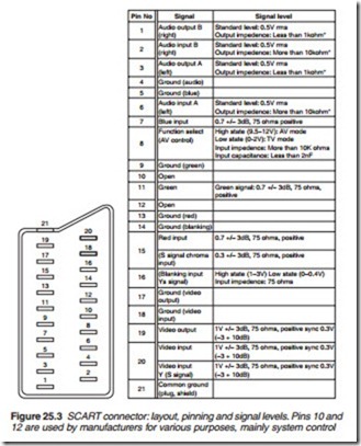
The 21-pin SCART coupling system is a versatile one. Its plug connection is shown in Figure 25.3 together with pin assignments. The SCART con- nector is a 21-pin non-reversible device. There are 20 pins available for
connections with pin 21 connected to the skirt and hence the chassis pro- vided the overall screening for cable communication.
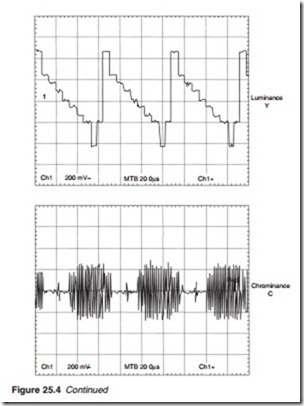
The SCART connector allows direct RGB connection to a TV receiver as well as CVBS together with independent stereo sound channel connections. It can also provide S- (separate Y/C) video. For a standard colour bar test signal, the expected waveforms at each of the video output (CVBS, red, green, blue and Y-C) are illustrated in Figure 25.4.
Pins 10 and 12 are used for intercommunications between devices con- nected to the SCART socket. Pin 8 carries out some control functions: when it goes high (9–12 V) it switches the TV to AV input, or a standing- by digital TV receiver to loop-through mode. At a level of about 6 V, it sig- nals the presence of a wide-screen picture from VCR or set-top box (STB) to a suitably equipped TV which switches scan generators accordingly. In
S-video mode, the luminance and sync signals are passed out on pin 19 and received on pin 20, while pin 15 conveys the C signal at a burst level of 300 mV. Switching between composite video and S-video is carried out at pin 16. TVs, DVD players and STBs can be programmed for the various signal modes, and it is important that the boxes at both ends of the cable are in agreement as to the mode in use; and that the best possible mode is selected, depending on the signal and source in use and the capabilities of the equipment involved. Thus RGB is appropriate to DVD players and large-screen TVs, while composite video is used by low-band (VHS, Video-8) machines.
Inexpensive SCART coupling leads have neither screened signal conduc- tors nor separate ground paths for them, giving rise to cross-talk. This is manifested as floating bars, outlines and/or colours on vision and
buzz/cross-talk on sound. The picture problems can often be solved by cut- ting off the connection to pin 19 in the SCART plug at the TV end, so long as no video-out signal is required from the TV tuner. The appropriation of SCART pins 10 and 12 by manufacturers for various purposes can lead to trouble, so it is best to either cut them or use leads in which they are not connected – unless the connection specifically requires their use. Indeed a fully wired SCART lead, heavy, thick and relatively expensive, is best avoided unless the application calls for it. Low-level applications involving just com- posite video and mono or stereo sound are best served by a lead with screened conductors at pins 1/2/3/6/19/20 (basically three crossed-over signal feeds) plus a link between pin 8. The control function of SCART pin 8, pulling the TV into AV mode, can be a nuisance where for example it is required to watch a TV programme while recording another from satellite. Often there is a TV/SAT key on the sat-box’s remote control to overcome this, but if necessary the lead can be cut from SCART pin 8, when signal input selection is under the sole control of the TV set’s remote handset.


