sampling structure
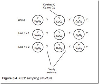
There are several structures for subsampling the chrominance components. One way is to sample the chrominance components every other pixel, known as 4:2:2 sampling structure (Figure 3.4). The 4:2:2 reduces the chrominance resolution in the horizontal dimension only, leaving the ver- tical resolution unaffected. The ratio 4:2:2 indicates that both CR and CB are sampled at half the rate of the luminance signal. Notice that the chromi- nance samples are evenly distributed across the picture, producing alter- nate Y-only columns and alternate co-sited (Y, CR and CB) columns. Where interlacing is used, the distribution of the chroma samples remains evenly distributed in each field (Figure 3.5).
sampling structure
To reduce the bandwidth, and hence lower the bit rate, a 4:1:1 sampling structure may be used. Here, the chrominance components are sampled at a quarter of the luminance rate (every forth pixel), hence the ratio 4:1:1 (Figure 3.6). The 4:1:1 sampling structure was used in early digital appli- cations with good results. However, it can be seen from Figure 3.6 that there is a large imbalance between the vertical and horizontal chromi- nance resolution. To overcome this while maintaining the same bit rate, the 4:2:0 sampling was introduced.
sampling structure
In this technique, subsampling at half full rate is used in both the horizontal and vertical direction, i.e. sampling every other pixel as well as every other line. The result is alternate Y-only columns as well as alternate Y-only rows as illustrated in Figure 3.7.
The above distribution of Y and co-sited samples are adequate for a sequentially scanned TV picture whereby chrominance samples are distributed evenly across the complete TV picture. However, this technique fails with interlaced pictures. The reason is as follows. Since the chrominance samples are taken every other line, lines 1, 3, 5, and so on, they belong to one field only (the top field) with none taken from the next field (the bottom field). To overcome this, sample interpolation is used to obtain an even spread of the chroma information. Interpolation involves deducing a single chrominance sample by averaging the chrominance values of two adjacent lines in one field, and inserting the sample halfway between two lines from successive fields. Even distribution of the chrominance samples may thus be realised when the two fields are combined.


