PCM RECORDING
Pulse-code recording is based on a quantisation process in which the analogue signal (here the audio waveform) is regularly sampled at a rate at least twice as high as its likely maximum frequency. The level obtained at each sampling point is applied to an A-D converter, which for audio applications needs to have at least 10-bit resolution to give 1024-level sampling. For V8 format, where it is a high-quality alternative to the mono-f.m. system described above, the 10-bit digital signal is brought down to 8 bits by a sophisticated bit-reduction technique. Even so, eight bits within 32 μs (corresponding to 2f h, 31.25 kHz sampling rate) equates to a bit-rate of around 250 000 per second, requiring a bandwidth too great to accommodate in any form of track-multiplexing system so far described in this chapter.
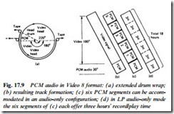
For videotape recording the digitised audio signal is read into a memory continuously, and read out at about seven times speed. This ‘compresses’ the signal up to a bit-rate of about 2 Mbit/sec, but leaves a long waiting period between readout periods – the process is similar to that used in the MAC TV transmission system described in Chapter 4. To accommodate the PCM-stereo track on the V8 tape the effective head wrap is increased from 180° to 220° (Fig. 17.9(a)) to increase the length of the video head sweep, the first 30° or so of which are used for PCM audio recording, with the recording (and subsequent playback) video amplifiers switched to the digital audio- memory for this brief period. Fig. 17.9(b) shows the part of the tape reserved for PCM audio; it forms an extension of the video track area.
The digital PCM signal recorded on tape contains correction (par- ity) bits to permit repair of a corrupted digital signal, as is common practice in digital coding systems – mention of this was made in con- nection with videotext transmission in Chapter 8. To further protect against corruption resulting from tape dropout effects the digital signal is scattered according to a precisely defined code during record. The effect is analogous to that of shuffling a pack of cards: adjacent segments of the digital pulse train are recorded at widely different physical positions on tape. During replay an ‘unshufflng’ process takes place, in which the PCM segments are once more rearranged in correct order, but now with any damage due to dropouts etc. distributed throughout the data pulse train, and nowhere so bad that the inbuilt correction/parity check bits cannot adequately restore the output signal. The process is identical in principle to that used in the Nicam transmissions described in Chapter 9.
Further details of the V8 PCM sound signal are as follows: the baseband audio signal is compressed to 1:2 before quantisation and expanded 2:1 after D-A conversion in a logarithmic compander like those already described in connection with Hi-Fi f.m. sound systems. This raises the 48 dB dynamic range ordinarily available from an 8-bit quantisation system to the equivalent of 13 bits, comparable to the 14-bit system used in EIAJ PCM format and the 16-bit Compact Disc system, which latter is wholly dedicated to sound and represents one of the highest quality (<90 dB dynamic range) programme reproduction systems available in domestic entertainment equipment. Error correction in V8 format PCM is carried out by two interleaving error correction codes on each data block every 8-bit word; this is called a Cross-Interleave Code (CIC). The audio sampling rate is twice line frequency: 31.25 kHz for PAL/625, 31.5 kHz for NTSC/525. Data words are recorded for each field as 625/2 × (2 × 2) = 1250 for PAL, and 525/2 × (2 × 2) = 1050 for NTSC. The compressed digital audio signal is f.m.-modulated for recording via the video heads, and similarly demodulated during replay.
