COLOUR PICTURE TUBE
To build up a colour picture three separate primary colours are used – red, green and blue. Combinations of these three can make almost any colour, including white; by adjusting the three colour intensities to obtain white and then regulating the brightness of all three together different brightnesses of white can be achieved, permitting the reproduction of a monochrome picture if required.
The construction of a colour tube is shown in Fig. 5.3. A single gun is used, working in similar fashion to the monchrome gun assembly already described, but containing three separate but closely spaced cathodes. These cathodes are mounted in-line abreast, and the other electrodes in the gun assembly each have a row of three pinholes aligned with the electron beams emerging from the triple cathode array. As the three beams travel along the tube neck they are accelerated and focused by the anodes in the gun assembly, each to come to a sharp point of focus at the surface of the screen.
Colour screen
The rear of the screen of a colour picture tube is composed of a large number (typically 600 across the screen width of a large tube) of vertical stripes of phosphor material. The stripes are laid in the
sequency RGBRGB etc. across the screen width. Red-emitting phosphors are made of a rare-earth material yttrium/oxysulphide/ europium, while the other two are based on zinc sulphide with silver admix for blue and a copper/aluminium admix for green. The rear surface of the phosphor layer is aluminised, the thin coat of aluminium reflecting the phosphor light forward, equalising the electrical charge over the screen area, and preventing ion burn to the phosphors. The rear (gun side) of the aluminising layer is sprayed black to help in dissipating the heat developed by the shadowmask and screen.
Shadowmask
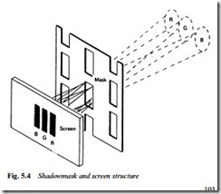
Mounted some 12 mm behind the tricolour phosphor layer is the shadowmask (Fig. 5.4). The shadowmask is the main feature of all direct-viewing colour picture tubes and its function is to act as a filter, permitting the electron beam from each cathode to strike only its own phosphor material. As they approach the screen the three separate beams are on converging paths, with approach angles typi- cally 1° apart. The beams cross over as they pass through the slots in the mask, and diverge beyond to impinge on their respective phosphor stripes. For each phosphor stripe the ‘wrong’ electron beams are shadowed by the mask, so that each beam (provided its approach angle is correct) can only see through the mask to its own phosphor stripe, and this applies regardless of the degree of deflection it suffers in its passage through the deflection field. Thus is set up the condition whereby three separate but superimposed fields of primary colour, red, green and blue, can be produced on a single screen, each field being separately controlled by the bias applied to its own cathode with respect to the common grid plate.
The shadowmask is inherently inefficient in that most of the energy in the three beams is intercepted by the steel mask itself; only about 25% of the beams’ energy reaches the phosphors, the rest being dis- sipated as heat in the mask itself. On very high brightness scenes the dissipation in the mask can exceed 20 W, and the effect of the result- ing heat is to expand the mask. Any resulting buckling or distortion will upset beam landing accuracy and lead to impurity, in which the beams strike the wrong phosphor stripes, staining the picture with patches of incorrect colour. To prevent this the shadowmask is secured to the inside of the glass envelope by special mountings which
permit the expansion to be taken up by moving the entire mask axi- ally (i.e. towards or away from the screen) in such a way that beam landing accuracy is maintained. A typical mask mounting arrangement is shown in Fig. 5.5.
In the tube manufacturing process the mask and screen are aligned and fitted to a ‘lighthouse’ machine to fix the phosphors. In a three- stage process, phosphor material for each colour is coated over the entire screen area then ‘fixed’ in the correct shape, width and position by shining a powerful xenon lamp through the mask. Since the light source is in exactly the position subsequently occupied by the apparent beam origin for each phosphor in turn, provided that the beams are correctly positioned and angled during the operation of the tube, perfect purity will result.


