IF AMPLIFIERS
As with the tuner, the i.f. amplifier has several functions, not all of them immediately obvious. Its primary task is to amplify the tuner’s output signal to a level where it can be practically demodulated. It is also required to maintain a constant output signal level in the face of very wide variations in signal input level; to provide a closely defined passband, selectively amplifying wanted signals and rejecting adjacent ones; to furnish a.g.c. and a.f.c. control lines for the tuner; and to offer a reasonably linear phase response or group- delay characteristic, important for colour reproduction and crucial to good teletext reception.
Bandpass shaping
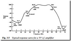
The tuner’s r.f. stage offers rejection of unwanted signals which are widely spaced from the carrier in use, but is not sufficiently selective to reject frequencies within a few MHz of it. Thus adjacent channel and other spurious signals emerge unscathed from the tuner and must be rejected in the i.f. stage. For use with a synchronous demodulator (see later) the required response curve is as shown in Fig. 3.5. Deep rejection notches are provided at 41.5 MHz (adjacent sound carrier) and 31.5 MHz (adjacent vision carrier), and a shallower one at 33.5 MHz, corresponding to the co-sound i.f. frequency. The need for the 33.5 MHz notch is twofold: to prevent a high level of sound carrier beating with the colour subcarrier at 35.07 MHz to produce a 1.57 MHz pattern on highly coloured areas of the picture; and to depress the sound carrier to a level where it remains below the minimum excursion of the vision signal (i.e. peak white) so that it will not become amplitude-modulated by picture frequencies to cause difficulties with buzz on sound.
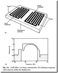
For many years conventional LC tuned circuits were used for filtering and bandshaping in i.f. circuits, which then typically consisted of a 3-stage transistor amplifier feeding a simple diode detector. TV and videorecorder receivers now use a SAW (Surface Acoustic Wave) filter for the purpose. An idea of its construction is given in Fig. 3.6. An
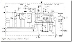
input signal transducer converts the incoming electrical signal to an acoustic wave which is propagated across the surface of a piezoelectric substrate. Its ease of passage depends on the frequency involved – the design of the resonant transducers is such that the response curve of Fig. 3.5 is closely maintained. The most critical area is around the vision i.f. frequency of 39.5 MHz, where the output signal should be exactly 6 dB down from full gain, see Fig. 3.6(b). The use of a SAWF greatly simplifies the fabrication and setting up of the i.f. amplifier, as can be seen in the typical circuit of Fig. 3.7. Here the i.f. input signal is amplified by about 26 dB within IC50 before application to the SAWF, whose output passes direct to the balanced inputs of IC51.
Although this type of circuit has now been superseded by direct drive of the SAWF from the tuner and more comprehensive i.f. chips, it better illustrates the principles involved, particularly in the next section.
Amplification and detection
The TDA2540 chip IC51 contains amplifier, demodulator, a.g.c. and a.f.c. stages, together with some noise-reducing circuitry. The level of the recovered video signal is sampled in the a.g.c. detector, which regulates the amplifier gain to maintain constant output level. Normally the UHF tuner is kept at full gain to minimise noise, but when the TDA2540 chip is turned fully down (at an r.f. input level of around 5 mV) control over the tuner gain takes place via IC pin 4. The onset of r.f. a.g.c. is governed by the crossover control VR36. L36 is associated with the vision demodulator and is tuned with C45 to the vision i.f. of 39.5 MHz. If the i.f. frequency increases, the potential at IC pin 5 reduces and vice versa, and this is fed back to the tuner’s tuning voltage input to form an a.f.c. loop; a defeat line is provided at IC pin 6 whereby the a.f.c. action can be cancelled when fine-tuning or changing channels. With the a.f.c. on, L36 is adjusted for correct tuning, thereafter compensating for ageing and thermal drift in the tuner’s local oscillator, or for carrier drift in any local r.f. signal source.
The demodulator works on the synchronous principle. A sample of carrier signal is amplified, clipped and applied to the ‘tank’ tuned circuit L34/C43. The result is a train of sampling pulses at 39.5 MHz, and these are used to gate the amplitude-modulated vision i.f. signal, taking a sample of its level on each carrier cycle. The succession of these samples forms the demodulated vision signal. The synchronous demodulator is capable of linear operation and has good intermodulation performance.
The video signal is preamplified within the chip, whence it emerges on pin 12. At this point it carries a 6 MHz intercarrier sound signal – the product of the 33.5 MHz sound i.f. signal – which is removed from the video signal by bridged-T notch filter L32/C39/C40/R34. At point 4/8 in the diagram, then, appears the 1 V pk-pk CVBS signal in the form shown in Fig. 2.5.
All these principles are embodied in the multi-purpose ICs now used in receivers and in the integrated tuner/receiver modules often fitted to TVs and videorecorders.


