■ DIESEL CYCLE: THE IDEAL CYCLE FOR COMPRESSION-IGNITION ENGINES
The Diesel cycle is the ideal cycle for CI reciprocating engines. The CI engine, first proposed by Rudolph Diesel in the 1890s, is very similar to the SI engine discussed in the last section, differing mainly in the method of initiating combustion. In spark-ignition engines (also known as gasoline engines), the air–fuel mixture is compressed to a temperature that is below the autoignition temperature of the fuel, and the combustion process is initiated by
firing a spark plug. In CI engines (also known as diesel engines), the air is compressed to a temperature that is above the autoignition temperature of the fuel, and combustion starts on contact as the fuel is injected into this hot air. Therefore, the spark plug and carburetor are replaced by a fuel injector in diesel engines (Fig. 8–20).
In gasoline engines, a mixture of air and fuel is compressed during the compression stroke, and the compression ratios are limited by the onset of autoignition or engine knock. In diesel engines, only air is compressed during the compression stroke, eliminating the possibility of autoignition. Therefore, diesel engines can be designed to operate at much higher compression ratios,
typically between 12 and 24. Not having to deal with the problem of autoignition has another benefit: many of the stringent requirements placed on the gasoline can now be removed, and fuels that are less refined (thus less ex- pensive) can be used in diesel engines.
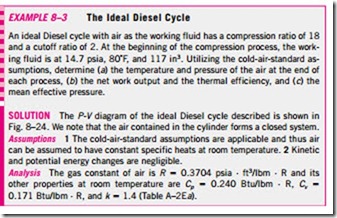
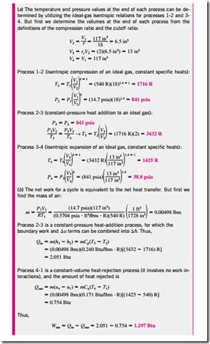
The fuel injection process in diesel engines starts when the piston approaches TDC and continues during the first part of the power stroke. Therefore, the combustion process in these engines takes place over a longer interval. Be- cause of this longer duration, the combustion process in the ideal Diesel cycle is approximated as a constant-pressure heat-addition process. In fact, this is the only process where the Otto and the Diesel cycles differ. The remaining three processes are the same for both ideal cycles. That is, process 1-2 is isentropic compression, 3-4 is isentropic expansion, and 4-1 is constant-volume heat rejection. The similarity between the two cycles is also apparent from the P–υ and T–s diagrams of the Diesel cycle, shown in Fig. 8–21.
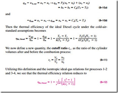
Noting that the Diesel cycle is executed in a piston-cylinder device, which forms a closed system, the amount of heat transferred to the working fluid at constant pressure and rejected from it at constant volume can be expressed as
where r is the compression ratio defined by Eq. 8–9. Looking at Eq. 8–12 carefully, one would notice that under the cold-air-standard assumptions, the efficiency of a Diesel cycle differs from the efficiency of an Otto cycle by the quantity in the brackets. This quantity is always greater than 1. Therefore,
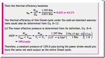
when both cycles operate on the same compression ratio. Also, as the cutoff ratio decreases, the efficiency of the Diesel cycle increases (Fig. 8–22). For the limiting case of rc = 1, the quantity in the brackets becomes unity (can you prove it?), and the efficiencies of the Otto and Diesel cycles become identical. Remember, though, that diesel engines operate at much higher compression ratios and thus are usually more efficient than the spark-ignition (gasoline) engines. The diesel engines also burn the fuel more completely since they usually operate at lower revolutions per minute than spark-ignition engines. Thermal
efficiencies of large diesel engines range from about 35 to 40 percent.
The higher efficiency and lower fuel costs of diesel engines make them the clear choice in applications requiring relatively large amounts of power, such as in locomotive engines, emergency power generation units, large ships, and heavy trucks. As an example of how large a diesel engine can be, a 12-cylinder diesel engine built in 1964 by the Fiat Corporation of Italy had a normal power output of 25,200 hp (18.8 MW) at 122 rpm, a cylinder bore of 90 cm, and a stroke of 91 cm.
Approximating the combustion process in internal combustion engines as a constant-volume or a constant-pressure heat-addition process is overly simplistic and not quite realistic. Probably a better (but slightly more complex) approach would be to model the combustion process in both gasoline and diesel engines as a combination of two heat transfer processes, one at constant volume and the other at constant pressure. The ideal cycle based on this concept is called the dual cycle, and a P-υ diagram for it is given in Fig. 8–23. The relative amounts of heat transferred during each process can be adjusted to approximate the actual cycle more closely. Note that both the Otto and the Diesel cycles can be obtained as special cases of the dual cycle.


