■ RANKINE CYCLE: THE IDEAL CYCLE FOR VAPOR POWER CYCLES
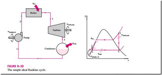
Many of the impracticalities associated with the Carnot cycle can be eliminated by superheating the steam in the boiler and condensing it completely in the condenser, as shown schematically on a T–s diagram in Fig. 8–39. The cy- cle that results is the Rankine cycle, which is the ideal cycle for vapor power plants. The ideal Rankine cycle does not involve any internal irreversibilities and consists of the following four processes:
1-2 Isentropic compression in a pump
2-3 Constant pressure heat addition in a boiler
3-4 Isentropic expansion in a turbine
4-1 Constant pressure heat rejection in a condenser
Water enters the pump at state 1 as saturated liquid and is compressed isentropically to the operating pressure of the boiler. The water temperature in- creases somewhat during this isentropic compression process due to a slight decrease in the specific volume of the water. The vertical distance between states 1 and 2 on the T-s diagram is greatly exaggerated for clarity. (If water were truly incompressible, would there be a temperature change at all during this process?)
Water enters the boiler as a compressed liquid at state 2 and leaves as a superheated vapor at state 3. The boiler is basically a large heat exchanger where the heat originating from combustion gases, nuclear reactors, or other sources is transferred to the water essentially at constant pressure. The boiler, together with the section where the steam is superheated (the superheater), is often called the steam generator.
The superheated vapor at state 3 enters the turbine, where it expands isentropically and produces work by rotating the shaft connected to an electric generator. The pressure and the temperature of the steam drop during this process to the values at state 4, where steam enters the condenser. At this state, steam is usually a saturated liquid–vapor mixture with a high quality. Steam is condensed at constant pressure in the condenser, which is basically a large heat exchanger, by rejecting heat to a cooling medium such as a lake, a river, or the atmosphere. Steam leaves the condenser as saturated liquid and enters the pump, completing the cycle. In areas where water is precious, the power plants are cooled by air instead of water. This method of cooling, which is also used in car engines, is called dry cooling. Several power plants in the world, including some in the United States, use dry cooling to conserve water.
Remembering that the area under the process curve on a T–s diagram represents the heat transfer for internally reversible processes, we see that the area under process curve 2-3 represents the heat transferred to the water in the boiler and the area under the process curve 4-1 represents the heat rejected in the condenser. The difference between these two (the area enclosed by the cycle curve) is the net work produced during the cycle.
Energy Analysis of the Ideal Rankine Cycle
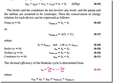
All four components associated with the Rankine cycle (the pump, boiler, turbine, and condenser) are steady-flow devices, and thus all four processes that make up the Rankine cycle can be analyzed as steady-flow processes. The kinetic and potential energy changes of the steam are usually small relative to the work and heat transfer terms and are therefore usually neglected. Then the steady-flow energy equation per unit mass of steam reduces to
The conversion efficiency of power plants in the United States is often ex- pressed in terms of heat rate, which is the amount of heat supplied, in Btu’s, to generate 1 kWh of electricity. The smaller the heat rate, the greater the efficiency. Considering that 1 kWh = 3412 Btu and disregarding the losses associated with the conversion of shaft power to electric power, the relation between the heat rate and the thermal efficiency can be expressed as
For example, a heat rate of 11,363 Btu/kWh is equivalent to 30 percent efficiency.
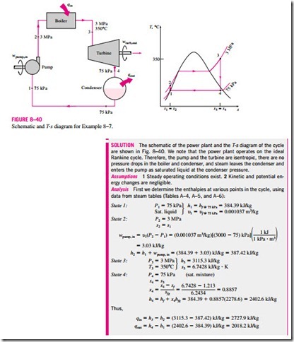
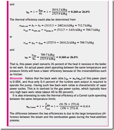
The thermal efficiency can also be interpreted as the ratio of the area en- closed by the cycle on a T–s diagram to the area under the heat-addition process. The use of these relations is illustrated in the following example.


