■ VIEW FACTOR RELATIONS
Radiation analysis on an enclosure consisting of N surfaces requires the evaluation of N2 view factors, and this evaluation process is probably the most time-consuming part of a radiation analysis. However, it is neither practical nor necessary to evaluate all of the view factors directly. Once a sufficient number of view factors are available, the rest of them can be determined by utilizing some fundamental relations for view factors, as discussed next.
We have shown earlier the pair of view factors Fi ® j and Fj ® i are related to each other by
This relation is referred to as the reciprocity relation or the reciprocity rule, and it enables us to determine the counterpart of a view factor from a knowledge of the view factor itself and the areas of the two surfaces. When deter- mining the pair of view factors Fi ® j and Fj ® i, it makes sense to evaluate first the easier one directly and then the more difficult one by applying the reciprocity relation.
2 The Summation Rule
The radiation analysis of a surface normally requires the consideration of the radiation coming in or going out in all directions. Therefore, most radiation problems encountered in practice involve enclosed spaces. When formulating a radiation problem, we usually form an enclosure consisting of the surfaces interacting radiatively. Even openings are treated as imaginary surfaces with radiation properties equivalent to those of the opening.
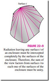
The conservation of energy principle requires that the entire radiation leaving any surface i of an enclosure be intercepted by the surfaces of the enclosure. Therefore, the sum of the view factors from surface i of an en- closure to all surfaces of the enclosure, including to itself, must equal unity. This is known as the summation rule for an enclosure and is expressed as (Fig. 22–9)
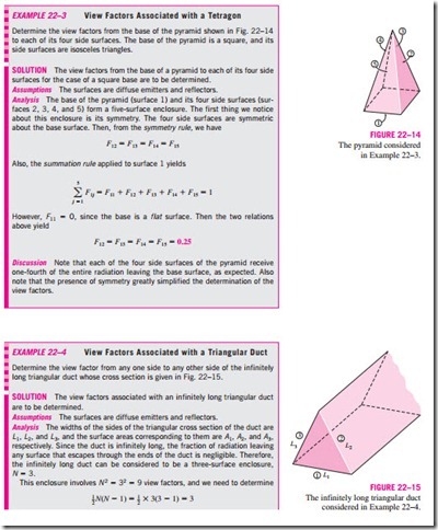
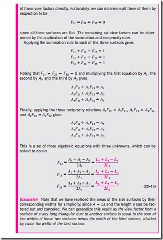
The summation rule can be applied to each surface of an enclosure by varying i from 1 to N. Therefore, the summation rule applied to each of the N surfaces of an enclosure gives N relations for the determination of the view factors. Also, the reciprocity rule gives 1 N(N – 1) additional relations. Then the total number of view factors that need to be evaluated directly for an N-surface enclosure becomes
3 The Superposition Rule
Sometimes the view factor associated with a given geometry is not available in standard tables and charts. In such cases, it is desirable to express the given geometry as the sum or difference of some geometries with known view fac- tors, and then to apply the superposition rule, which can be expressed as the view factor from a surface i to a surface j is equal to the sum of the view factors from surface i to the parts of surface j. Note that the reverse of this is not 3
true. That is, the view factor from a surface j to a surface i is not equal to the sum of the view factors from the parts of surface j to surface i.
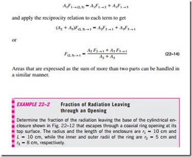
Consider the geometry in Fig. 22–11, which is infinitely long in the 2 direction perpendicular to the plane of the paper. The radiation that leaves surface 1 and strikes the combined surfaces 2 and 3 is equal to the sum of the radiation that strikes surfaces 2 and 3. Therefore, the view factor from surface 1 to the combined surfaces of 2 and 3 is
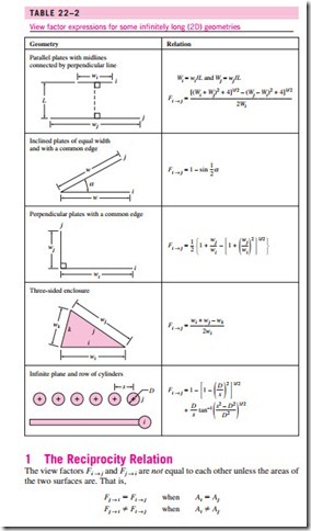
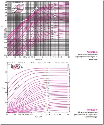
Suppose we need to find the view factor F1 ® 3. A quick check of the view factor expressions and charts in this section will reveal that such a view factor cannot be evaluated directly. However, the view factor F1 ® 3 can be deter- mined from Eq. 22–13 after determining both F1 ® 2 and F1 ® (2, 3) from the chart in Table 22–2. Therefore, it may be possible to determine some difficult view factors with relative ease by expressing one or both of the areas as the sum or differences of areas and then applying the superposition rule.
To obtain a relation for the view factor F(2, 3) ® 1, we multiply Eq. 22–13 by A1,
4 The Symmetry Rule
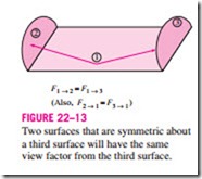
The determination of the view factors in a problem can be simplified further if the geometry involved possesses some sort of symmetry. Therefore, it is 3 good practice to check for the presence of any symmetry in a problem before attempting to determine the view factors directly. The presence of symmetry can be determined by inspection, keeping the definition of the view factor in mind. Identical surfaces that are oriented in an identical manner with respect to another surface will intercept identical amounts of radiation leaving that surface. Therefore, the symmetry rule can be expressed as two (or more) surfaces that possess symmetry about a third surface will have identical view factors from that surface (Fig. 22–13).
The symmetry rule can also be expressed as if the surfaces j and k are sym- metric about the surface i then Fi ® j = Fi ® k. Using the reciprocity rule, we can show that the relation Fj ® i = Fk ® i is also true in this case.
View Factors between Infinitely Long Surfaces: The Crossed-Strings Method
Many problems encountered in practice involve geometries of constant cross section such as channels and ducts that are very long in one direction relative to the other directions. Such geometries can conveniently be considered to be two-dimensional, since any radiation interaction through their end surfaces will be negligible. These geometries can subsequently be modeled as being infinitely long, and the view factor between their surfaces can be determined by the amazingly simple crossed-strings method developed by H. C. Hottel in the 1950s. The surfaces of the geometry do not need to be flat; they can be convex, concave, or any irregular shape.
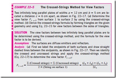
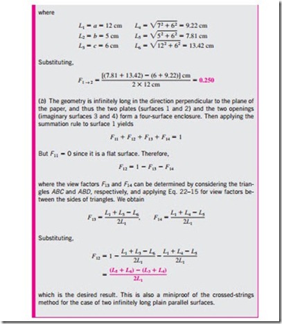
To demonstrate this method, consider the geometry shown in Fig. 22–16, and let us try to find the view factor F1 ® 2 between surfaces 1 and 2. The first thing we do is identify the endpoints of the surfaces (the points A, B, C, and D) and connect them to each other with tightly stretched strings, which are indicated by dashed lines. Hottel has shown that the view factor F1 ® 2 can be expressed in terms of the lengths of these stretched strings, which are straight lines, as
The crossed-strings method is applicable even when the two surfaces considered share a common edge, as in a triangle. In such cases, the common edge can be treated as an imaginary string of zero length. The method can also be applied to surfaces that are partially blocked by other surfaces by allowing the strings to bend around the blocking surfaces.
