Heat transfer in a heat exchanger usually involves convection in each fluid and conduction through the wall separating the two fluids. In the analysis of heat exchangers, it is convenient to work with an overall heat transfer coeffi- cient U that accounts for the contribution of all these effects on heat transfer. The rate of heat transfer between the two fluids at a location in a heat ex- changer depends on the magnitude of the temperature difference at that location, which varies along the heat exchanger. In the analysis of heat ex- changers, it is usually convenient to work with the logarithmic mean temperature difference LMTD, which is an equivalent mean temperature difference between the two fluids for the entire heat exchanger.
Heat exchangers are manufactured in a variety of types, and thus we start this chapter with the classification of heat exchangers. We then discuss the de- termination of the overall heat transfer coefficient in heat exchangers, and the LMTD for some configurations. We then introduce the correction factor F to account for the deviation of the mean temperature difference from the LMTD in complex configurations. Next we discuss the effectiveness–NTU method, which enables us to analyze heat exchangers when the outlet temperatures of the fluids are not known. Finally, we discuss the selection of heat exchangers
■ TYPES OF HEAT EXCHANGERS
Different heat transfer applications require different types of hardware and different configurations of heat transfer equipment. The attempt to match the heat transfer hardware to the heat transfer requirements within the specified constraints has resulted in numerous types of innovative heat exchanger designs.
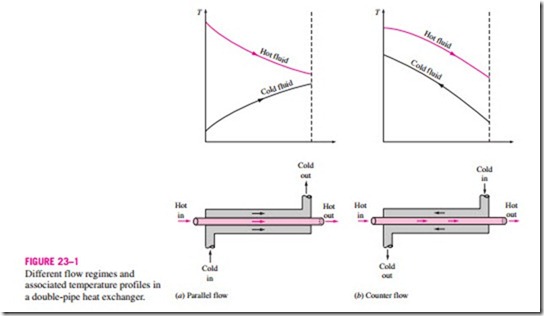
The simplest type of heat exchanger consists of two concentric pipes of different diameters, as shown in Fig. 23–1, called the double-pipe heat exchanger. One fluid in a double-pipe heat exchanger flows through the smaller pipe while the other fluid flows through the annular space between the two pipes. Two types of flow arrangement are possible in a double-pipe heat exchanger: in parallel flow, both the hot and cold fluids enter the heat exchanger at the same end and move in the same direction. In counter flow, on the other hand, the hot and cold fluids enter the heat exchanger at opposite ends and flow in opposite directions.
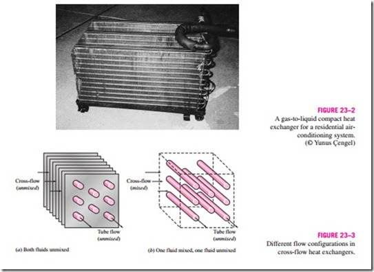
Another type of heat exchanger, which is specifically designed to realize a large heat transfer surface area per unit volume, is the compact heat ex- changer. The ratio of the heat transfer surface area of a heat exchanger to its volume is called the area density b. A heat exchanger with b > 700 m2/m3 (or 200 ft2/ft3) is classified as being compact. Examples of compact heat exchangers are car radiators (b = 1000 m2/m3), glass ceramic gas turbine heat exchangers (b = 6000 m2/m3), the regenerator of a Stirling engine (b = 15,000 m2/m3), and the human lung (b = 20,000 m2/m3). Compact heat exchangers enable us to achieve high heat transfer rates between two fluids in
a small volume, and they are commonly used in applications with strict limitations on the weight and volume of heat exchangers (Fig. 23–2).
The large surface area in compact heat exchangers is obtained by attaching closely spaced thin plate or corrugated fins to the walls separating the two flu- ids. Compact heat exchangers are commonly used in gas-to-gas and gas-to- liquid (or liquid-to-gas) heat exchangers to counteract the low heat transfer coefficient associated with gas flow with increased surface area. In a car radiator, which is a water-to-air compact heat exchanger, for example, it is no surprise that fins are attached to the air side of the tube surface.
In compact heat exchangers, the two fluids usually move perpendicular to each other, and such flow configuration is called cross-flow. The cross-flow is further classified as unmixed and mixed flow, depending on the flow con- figuration, as shown in Fig. 23–3. In (a) the cross-flow is said to be unmixed since the plate fins force the fluid to flow through a particular interfin spacing and prevent it from moving in the transverse direction (i.e., parallel to the tubes). The cross-flow in (b) is said to be mixed since the fluid now is free to move in the transverse direction. Both fluids are unmixed in a car radiator. The presence of mixing in the fluid can have a significant effect on the heat transfer characteristics of the heat exchanger.
Perhaps the most common type of heat exchanger in industrial applications is the shell-and-tube heat exchanger, shown in Fig. 23–4. Shell-and-tube heat exchangers contain a large number of tubes (sometimes several hundred) packed in a shell with their axes parallel to that of the shell. Heat transfer takes place as one fluid flows inside the tubes while the other fluid flows outside the tubes through the shell. Baffles are commonly placed in the shell to force the shell-side fluid to flow across the shell to enhance heat transfer and to maintain uniform spacing between the tubes. Despite their widespread use, shell- and-tube heat exchangers are not suitable for use in automotive and aircraft applications because of their relatively large size and weight. Note that the tubes in a shell-and-tube heat exchanger open to some large flow areas called headers at both ends of the shell, where the tube-side fluid accumulates before entering the tubes and after leaving them.
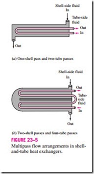
Shell-and-tube heat exchangers are further classified according to the number of shell and tube passes involved. Heat exchangers in which all the tubes make one U-turn in the shell, for example, are called one-shell-pass and two- tube-passes heat exchangers. Likewise, a heat exchanger that involves two passes in the shell and four passes in the tubes is called a two-shell-passes and four-tube-passes heat exchanger (Fig. 23–5).
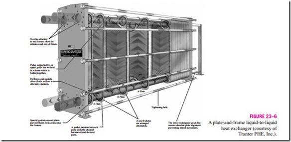
An innovative type of heat exchanger that has found widespread use is the plate and frame (or just plate) heat exchanger, which consists of a series of plates with corrugated flat flow passages (Fig. 23–6). The hot and cold fluids flow in alternate passages, and thus each cold fluid stream is surrounded by two hot fluid streams, resulting in very effective heat transfer. Also, plate heat exchangers can grow with increasing demand for heat transfer by simply mounting more plates. They are well suited for liquid-to-liquid heat exchange applications, provided that the hot and cold fluid streams are at about the same pressure.
Another type of heat exchanger that involves the alternate passage of the hot and cold fluid streams through the same flow area is the regenerative heat ex- changer. The static-type regenerative heat exchanger is basically a porous mass that has a large heat storage capacity, such as a ceramic wire mesh. Hot and cold fluids flow through this porous mass alternatively. Heat is transferred from the hot fluid to the matrix of the regenerator during the flow of the hot fluid, and from the matrix to the cold fluid during the flow of the cold fluid. Thus, the matrix serves as a temporary heat storage medium.
The dynamic-type regenerator involves a rotating drum and continuous flow of the hot and cold fluid through different portions of the drum so that any portion of the drum passes periodically through the hot stream, storing heat, and then through the cold stream, rejecting this stored heat. Again the drum serves as the medium to transport the heat from the hot to the cold fluid stream.
Heat exchangers are often given specific names to reflect the specific application for which they are used. For example, a condenser is a heat exchanger in which one of the fluids is cooled and condenses as it flows through the heat exchanger. A boiler is another heat exchanger in which one of the fluids absorbs heat and vaporizes. A space radiator is a heat exchanger that transfers heat from the hot fluid to the surrounding space by radiation.


