THE OVERALL HEAT TRANSFER COEFFICIENT
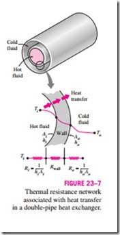
A heat exchanger typically involves two flowing fluids separated by a solid wall. Heat is first transferred from the hot fluid to the wall by convection, through the wall by conduction, and from the wall to the cold fluid again by convection. Any radiation effects are usually included in the convection heat transfer coefficients.
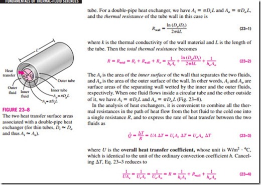
The thermal resistance network associated with this heat transfer process involves two convection and one conduction resistances, as shown in Fig. 23–7. Here the subscripts i and o represent the inner and outer surfaces of the inner tube. For a double-pipe heat exchanger, we have Ai = pDi L and Ao = pDo L, and the thermal resistance of the tube wall in this case is
Perhaps you are wondering why we have two overall heat transfer coefficients Ui and Uo for a heat exchanger. The reason is that every heat exchanger has two heat transfer surface areas Ai and Ao, which, in general, are not equal to each other.
Note that Ui Ai = Uo Ao, but Ui * Uo unless Ai = Ao. Therefore, the overall heat transfer coefficient U of a heat exchanger is meaningless unless the area on which it is based is specified. This is especially the case when one side of the tube wall is finned and the other side is not, since the surface area of the finned side is several times that of the unfinned side.
When the wall thickness of the tube is small and the thermal conductivity of the tube material is high, as is usually the case, the thermal resistance of the tube is negligible (Rwall = 0) and the inner and outer surfaces of the tube are almost identical (Ai = Ao = As). Then Eq. 23–4 for the overall heat transfer coefficient simplifies to
where U = Ui = Uo. The individual convection heat transfer coefficients inside and outside the tube, hi and ho, are determined using the convection relations discussed in earlier chapters.
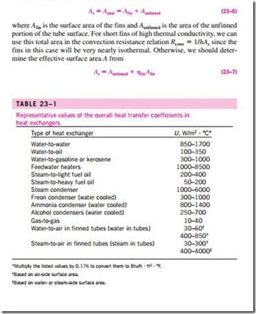
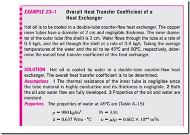
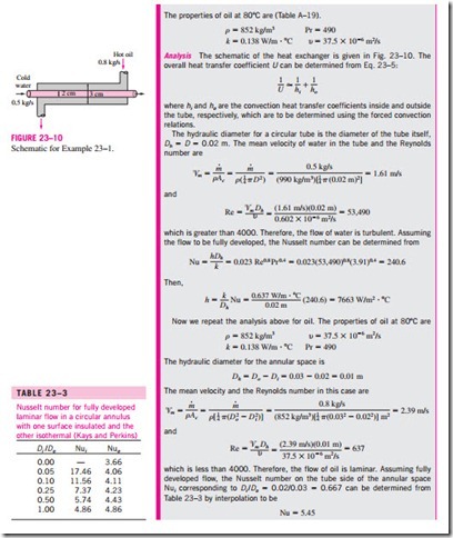
The overall heat transfer coefficient U in Eq. 23–5 is dominated by the smaller convection coefficient, since the inverse of a large number is small. When one of the convection coefficients is much smaller than the other (say, hi � ho), we have 1/hi � 1/ho, and thus U = hi. Therefore, the smaller heat transfer coefficient creates a bottleneck on the path of heat flow and seriously impedes heat transfer. This situation arises frequently when one of the fluids is a gas and the other is a liquid. In such cases, fins are commonly used on the gas side to enhance the product UAs and thus the heat transfer on that side. Representative values of the overall heat transfer coefficient U are given in Table 23–1. Note that the overall heat transfer coefficient ranges from about 10 W/m2 · °C for gas-to-gas heat exchangers to about 10,000 W/m2 · °C for heat exchangers that involve phase changes. This is not surprising, since gases have very low thermal conductivities, and phase-change processes involve very high heat transfer coefficients.
When the tube is finned on one side to enhance heat transfer, the total heat transfer surface area on the finned side becomes
where hfin is the fin efficiency. This way, the temperature drop along the fins is accounted for. Note that hfin = 1 for isothermal fins, and thus Eq. 23–7 reduces to Eq. 23–6 in that case.
Fouling Factor
The performance of heat exchangers usually deteriorates with time as a result of accumulation of deposits on heat transfer surfaces. The layer of deposits represents additional resistance to heat transfer and causes the rate of heat transfer in a heat exchanger to decrease. The net effect of these accumulations on heat transfer is represented by a fouling factor Rf , which is a measure of the thermal resistance introduced by fouling.
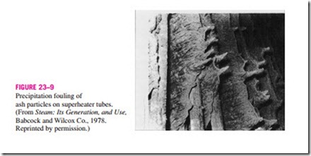
The most common type of fouling is the precipitation of solid deposits in a fluid on the heat transfer surfaces. You can observe this type of fouling even in your house. If you check the inner surfaces of your teapot after prolonged use, you will probably notice a layer of calcium-based deposits on the surfaces at which boiling occurs. This is especially the case in areas where the water is hard. The scales of such deposits come off by scratching, and the surfaces can be cleaned of such deposits by chemical treatment. Now imagine those mineral deposits forming on the inner surfaces of fine tubes in a heat exchanger (Fig. 23–9) and the detrimental effect it may have on the flow passage area and the heat transfer. To avoid this potential problem, water in power and process plants is extensively treated and its solid contents are removed before it is allowed to circulate through the system. The solid ash particles in the flue gases accumulating on the surfaces of air preheaters create similar problems. Another form of fouling, which is common in the chemical process industry, is corrosion and other chemical fouling. In this case, the surfaces are fouled by the accumulation of the products of chemical reactions on the surfaces. This form of fouling can be avoided by coating metal pipes with glass or using plastic pipes instead of metal ones. Heat exchangers may also be fouled by the growth of algae in warm fluids. This type of fouling is called biological fouling and can be prevented by chemical treatment.
In applications where it is likely to occur, fouling should be considered in the design and selection of heat exchangers. In such applications, it may be necessary to select a larger and thus more expensive heat exchanger to ensure that it meets the design heat transfer requirements even after fouling occurs. The periodic cleaning of heat exchangers and the resulting down time are additional penalties associated with fouling.
The fouling factor is obviously zero for a new heat exchanger and increases with time as the solid deposits build up on the heat exchanger surface. The fouling factor depends on the operating temperature and the velocity of the fluids, as well as the length of service. Fouling increases with increasing temperature and decreasing velocity.
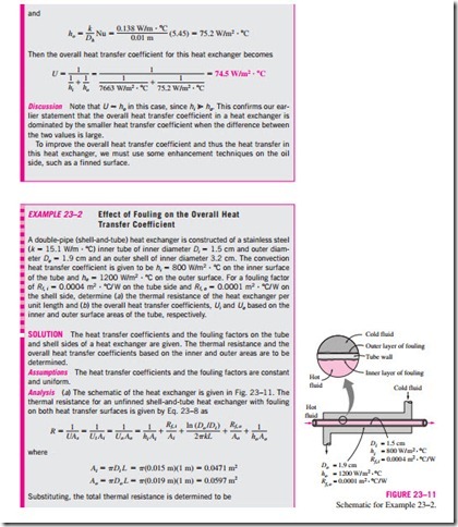
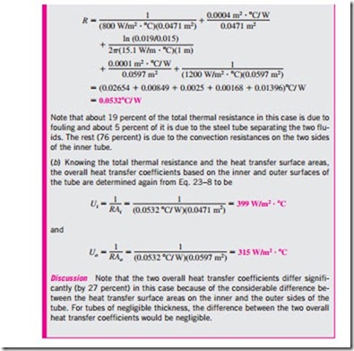
The overall heat transfer coefficient relation given above is valid for clean surfaces and needs to be modified to account for the effects of fouling on both the inner and the outer surfaces of the tube. For an unfinned shell-and-tube heat exchanger, it can be expressed as
where Ai = pDi L and Ao = pDo L are the areas of inner and outer surfaces, and Rf, i and Rf, o are the fouling factors at those surfaces.
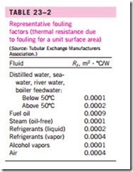
Representative values of fouling factors are given in Table 23–2. More comprehensive tables of fouling factors are available in handbooks. As you would expect, considerable uncertainty exists in these values, and they should be used as a guide in the selection and evaluation of heat exchangers to account for the effects of anticipated fouling on heat transfer. Note that most fouling factors in the table are of the order of 10-4 m2 · °C/W, which is equivalent to the thermal resistance of a 0.2-mm-thick limestone layer (k = 2.9 W/m · °C) per unit surface area. Therefore, in the absence of specific data, we can assume the surfaces to be coated with 0.2 mm of limestone as a starting point to account for the effects of fouling.
