Line Loss and Voltage Drop Relationships
Line losses are from the line current flowing through the resistance of the conductors. After distribution transformer losses, primary line losses are the largest cause of losses on the distribution system. Like any resistive losses, line losses are a function of the current squared multiplied by the resistance (I2R). Ways to reduce line losses include
• Use a higher system voltage
• Balance circuits
• Convert single-phase circuits to three-phase circuits
• Reduce loads
• Increase power factor (capacitors)
• Reconductor with a larger size
Because losses are a function of the current squared, most losses occur on the primary near the substation. Losses occur regardless of the power factor of the circuit. Reducing the reactive portion of current reduces the total current, which can significantly impact losses.
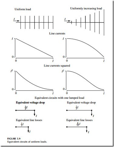
Approximations using uniform load distributions are useful. A uniformly distributed load along a circuit of length l has the same losses as a single lumped load placed at a length of l/3 from the source end. For voltage drop, the equivalent circuits are different: a uniformly distributed load along a circuit of length l has the same voltage drop as a single lumped load placed at a length of l/2 from the source end. This 1/2 rule for voltage drop and the 1/3 rule for losses are helpful approximations when doing hand calcu- lations or when making simplifications to enter in a load-flow program.
For a uniformly increasing load, the equivalent lumped load is at 0.53l of the length from the source. Figure 5.9 shows equivalent circuits for a uniform load and a uniformly increasing load.
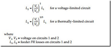
Line losses decrease as operating voltage increases because the current decreases. Schultz (1978) derived several expressions for primary feeder I2R losses on circuits with uniform load densities. His analysis showed that most 15 to 35 kV circuits are not voltage-drop limited — most are thermally limited. As the system voltage varies, the losses change the most for voltage- limited circuits (Schultz, 1978):
On a system-wide basis, losses are expected to change with voltage with an exponent somewhere between 2/3 and 2.
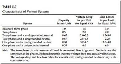
Losses, voltage drop, and capacity are all interrelated. Three-phase circuits have the highest power transfer capacity, the lowest voltage drop, and the lowest losses. Table 5.7 compares capacity, voltage drop, and losses of a balanced three-phase system with several other phasing configurations.
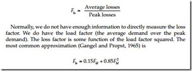
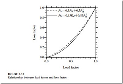
Utilities consider both peak losses and energy losses. Peak losses are important because they compose a portion of the peak demand; energy losses are the total kilowatt-hours wasted as heat in the conductors. The peak losses are more easily estimated from measurements and models. The average losses can be found from the peak losses using the loss factor Fls:
This is often used for evaluating line losses and transformer load losses (which are also a function of I2R). Load factors closer to one result in loss factors closer to one. Another common expression is
Related posts:
Incoming search terms:
- distribution power and voltage drop relationship
- relation load and line loss
- relation between % voltage drop and power loss
- derive the relation for voltage drop and power loss
- voltage regulation losses
- voltage drop and voltage regulation relation
- relation between voltage drop and voltage regulation
- Relation between voltage drop and loads
- line losses voltage drop
- how to line loss using regulation
- difference between voltage regulation and voltage drop
- what is difference between voltage regulation and voltage drop in line
