Utility AC Power System Architecture
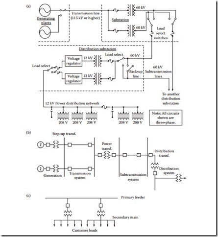
The details of power distribution vary from one city or country to another, and from one utility company to another, but the basics are the same. Figure 1.9 shows a simplified distribution network. Power from a generating station or distribution grid comes into an area substation at 115 kV or higher. The substation consists of switching systems, step-down transformers, fuses, circuit breakers, reclosers, monitors, and control equipment. The substation delivers output voltages of approximately 60 kV to subtransmission circuits, which feed distribution substations. The substations convert the energy to approximately 12 kV and provide voltage regulation and switching provisions that permit patching around a problem. The 12 kV lines power pole- and surface-mounted transformers, which supply various voltages to individual loads. Typical end-user voltage configurations include:
• 120/208 V wye
• 277/480 V wye
• 120/240 V single phase
• 480 V delta
The circuits feeding individual customer loads are referred to as the secondary system, whereas the primary system is the network upstream from the secondary (Figure 1.9c). The secondary system origi- nates at the distribution transformer and ends at the consumer loads. Each secondary main may supply groups of customers. In some instances, where service reliability is incorporated into the design, the secondary mains of several adjacent transformers may be connected through a fuse or a recloser. This is referred to as secondary banking. If an even higher service reliability factor is required, the secondary mains in an area can be connected in a mesh or a network, similar to the networking of the primary.
Fuses and circuit breakers are included at a number of points in the distribution system to minimize fault-caused interruptions of service. Ground-fault interrupters (GFIs) are also included at various points in the 12 kV system to open the circuit if excessive ground currents begin to flow on the monitored line. (GFIs are also known as ground-fault current interrupters, or GFCIs.) Reclosers may be included as part
Figure 1.9 Simplified block diagram of a basic utility company power distribution system: (2) Overall network. The devices shown as fuses could be circuit breakers or reclosers. All circuits shown are three-phase. The capacitors perform power factor correction duty. (b) System terminology. (c) Distinction between the primary and secondary distribution systems. (b and c from [3]. Used with permission.)
of overcurrent protection of the 12 kV lines. They will open the circuit if excessive currents are detected and reclose after a preset length of time, as discussed in the previous section.
In some areas, the actions of circuit breakers, pole-mounted switches, and reclosers are controlled by two-way radio systems that allow status interrogation and switching of the remotely located devices from a control center. Some utilities use this method sparingly; others make extensive use of it.
 Depending on the geographic location, varying levels of lightning protection are included as part of the ac power-system design. Most service drop transformers (12 kV to 208 V) have integral lightning arresters. In areas of severe lightning, a ground (or shield) wire is strung between the top insulators of each pole, diverting the lightning to the ground wire, and away from the hot leads.
Standard transmission voltages are established in the U.S. by the American National Standards Institute (ANSI). There is no clear delineation between distribution, subtransmission, and transmission volt- age levels. Table 1.4 lists the standard voltages given in ANSI Standards C84 and C92.2.
Power Distribution
The distribution of power over a utility company network is a complex process involving a number of power-generating plants, transmission lines, and substations. The physical size of a metropolitan power- distribution and control system is immense. Substations use massive transformers, oil-filled circuit breakers, huge strings of insulators, and high-tension conductors in distributing power to customers. Power-distribution and -transmission networks interconnect generating plants into an area grid, to which area loads are attached. Most utility systems in the U.S. are interconnected to one extent or another. In this way, power-generating resources can be shared as needed. The potential for single-point failure also is reduced in a distributed system.
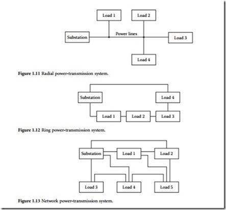
A typical power-distribution network is shown in Figure 1.10. Power transmission lines operate at voltage levels from 2.3 kV for local distribution to 500 kV or more for distribution between cities or generating plants. Long-distance, direct current transmission lines also are used, with potentials of 500 kV and higher. Underground power lines are limited to short runs in urban areas. Increased installation costs and cable heat-management considerations limit the use of high-voltage underground lines. Wide variations in standard voltage levels can be found within any given system. Each link in the network is designed to transfer energy with the least I 2R loss, thereby increasing overall system efficiency. The fol- lowing general classifications of power-distribution systems can be found in common use:
• Radial system. The simplest of all distribution networks, a single substation supplies power to all loads in the system. (See Figure 1.11.)
• Ring system. Distribution lines encircle the service area, with power being delivered from one or more sources into substations near the service area. Power is then distributed from the substations through the radial transmission lines. (See Figure 1.12.)
• Network system. A combination of the radial and ring distribution systems. Although such a system is more complex than either of the previous configurations, reliability is improved significantly. The net- work system, illustrated in Figure 1.13, is one of the most common power-distribution configurations.
Distribution Substations
Distribution substations serve as the source for primary distribution feeders [3]. They receive bulk electric power at high voltages and reduce the voltage to distribution primary values. Also associated with a substation are provisions for protection from faults, for voltage regulation, and for data acquisition and monitoring. The equipment generally installed in a distribution substation includes:
• Power transformers
• Oil or air circuit breakers
• Voltage regulators
• Protective relays
• Air break and disconnect switches
• Surge arresters
• Measuring instruments
• Storage batteries and capacitors (in some installations)
Some substations are entirely enclosed in buildings, whereas others are built entirely in the open with all equipment enclosed in one or more metal-clad units. The final design of the type of substation depends on economic factors; future load growth; and environmental, legal, and social issues.
Breaker Schemes
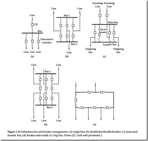
The circuit breaker scheme used at a substation provides for varying degrees of reliability and maintain- ability on both the input and output sides [3]. Each additional circuit breaker provides greater reliability and flexibility in maintaining the bus energized during a fault or during maintenance. However, the cost also increases with each circuit breaker. Hence, the selection of a particular substation scheme depends on safety, reliability, economy, and simplicity. The most commonly used circuit breaker schemes are [9]:
• The single-bus, shown in Figure 1.14a
• Double-bus/double-breaker, shown in Figure 1.14b
• Main-and-transfer bus, shown in Figure 1.14c
• Breaker-and-a-half, shown in Figure 1.14d
• Ring bus, shown in Figure 1.14e
Of these designs, the single-bus scheme costs the least; however, it possesses rather low reliability because the failure of the bus or any circuit breaker results in a total shutdown of the substation. The most expensive arrangement is the double-bus/double-breaker scheme. Each circuit is provided with two circuit breakers, and thus, any breaker can be taken out of service for maintenance without disruption of service at the substation. In addition, feeder circuits can be connected to either bus. The main-and-transfer bus requires an extra breaker for the bus tie between the main and the auxiliary buses. The breaker-and-a-half scheme provides the most flexible operation with high reliability. The relaying and automatic reclosing, however, are somewhat complex.
Voltage Analysis
Distribution systems are designed to maintain service voltages within specified limits during normal and emergency conditions. Typical voltage limits are [3]:
• For service to residential customers, the voltage at the point of delivery shall not exceed 5% above or below the nominal voltage. This is equivalent to the band between 114 and 126 V for most utilities in the United States.
• For service to commercial or industrial customers, the voltage at the point of delivery shall not exceed 7.5% above or below the nominal voltage.
• The maximum allowable voltage imbalance for a three-phase service shall be 2.5%.
The goal of voltage analysis is to determine whether the voltages on different line sections remain within the specified limits under varying load conditions. Thus, voltage analysis facilitates the effective placement of capacitors, voltage regulators, and other voltage regulation devices on the distribution sys- tem. Load flow analysis is a computer-aided tool that is typically used in this planning task. Load flows determine feeder voltages under steady-state conditions and at different load conditions.
Voltage analysis begins with an accurate representation, or map, of the feeder circuits, starting at the substation. The map generally consists of details and electrical characteristics (such as kVA ratings, impedances, and other parameters) of the conductors and cables on the system, substation and distribution transformers, series and shunt capacitors, voltage regulators, and related devices.
Before the analysis can begin, feeder loading must be known. Several different methods can be used for this task. If the utility maintains a database on each customer connected to a distribution transformer, it can use the billing data to determine the kilowatt-hours supplied by each transformer for a given month. Methods can then be used to convert the kilowatt-hours to a noncoincident peak kilovoltampere demand for all distribution transformers connected on the feeder. If this information is not available, the kilovoltampere rating of the transformer and a representative power factor can be used as the load. With the metered demand at the substation, the transformer loads can be allocated, for each phase, such that the allocated loads plus losses will equal the metered substation demand.
Accurately representing the load types or models is an important issue in voltage analysis. Several load models are available, including:
• Spot and distributed loads
• Wye and delta connected loads
• Constant power, constant current, constant impedance, or a combination of these methods
High-Voltage DC Transmission
High-voltage dc (HVDC) transmission offers several advantages over alternating current for long-dis- tance power transmission and asynchronous interconnection between two ac systems, including the abil- ity to precisely control the power flow without inadvertent loop flows that can occur in an interconnected ac system [9]. HVDC transmission can be classified into one of three broad categories:
• Back-to-back systems
• Two-terminal, or point-to-point, systems
• Multiterminal systems
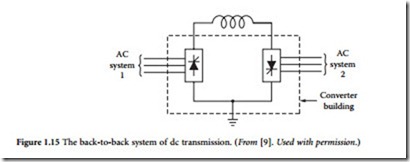
In a back-to-back dc system, shown in Figure 1.15, both the rectifier and the inverter are located in the same station, usually in the same building. The rectifier and inverter are usually integrated with a reactor, which is generally an air-core design. A back-to-back dc system is used to tie two asynchronous ac systems (systems that are not in synchronism). The two ac systems can be of different operating frequen- cies, for example, one 50 Hz and the other 60 Hz. Back-to-back dc links are also used to interconnect two ac systems that are of the same frequency but are not operating in synchronism. In North America, for example, Eastern and Western systems may not be synchronized, and Quebec and Texas may not be
synchronized with their neighboring systems. A dc link offers a practical solution to interconnecting these nonsynchronous networks.
Two-terminal dc systems can be either bipolar or monopolar. The bipolar configuration, shown in Figure 1.16a, is the commonly used arrangement for systems with overhead lines. In this configuration, there are two conductors, one for each polarity (positive and negative) carrying nearly equal currents. Only the difference of these currents, which is usually small, flows through the ground return. A monopolar system has one conductor, either of positive or negative polarity, with current returning through either ground or another metallic return conductor. The monopolar ground return current configuration, shown in Figure 1.16b, has been used for undersea cable systems, where current returns through the sea. This configuration can also be used for short-term emergency operation for a two-terminal dc line system in the event of a pole outage. However, concerns about corrosion of underground metallic struc- tures and interference with telephone and other utilities restrict the duration of such operation. The total ampere-hour operation per year is usually the restricting criterion. In a monopolar metallic return sys- tem, shown in Figure 1.16c, return current flows through a conductor, thus avoiding the problems associ- ated with ground return current. This method is generally used as a contingency mode of operation for a normal bipolar transmission system in the event of a partial converter (one-pole equipment) outage. In the case of outage of a one-pole converter, the conductor of the affected pole will be used as the return current conductor. A metallic return transfer breaker is opened, diverting the return current from the ground path and into the pole conductor. This conductor is grounded at one end and insulated at the other end. This system can transmit half the power of the normal bipolar system capacity, and can be increased if overload capacity is available. However, the percentage of losses will be doubled compared to the normal bipolar operation.
There are two basic configurations in which dc systems can be operated as multiterminal systems:
• Parallel configuration
• Series configuration
The parallel configuration can be either radial-connected (Figure 1.17a) or mesh-connected (Figure 1.17b). In a parallel-connected multiterminal dc system, all converters operate at the same nominal dc voltage, similar to ac system interconnections. In this mode of operation, one converter determines the operating voltage, and all other terminals operate in a current-controlling mode.
In a series-connected multiterminal dc system, shown in Figure 1.18, all converters operate at the same current. One converter sets the current that will be common to all converters in the system. Except for the converter that sets the current, the remaining converters operate in a voltage control mode (constant firing angle or constant extinction angle). The converters operate almost independently without the requirement for high-speed communication between them. The power output of a noncurrent-control- ling converter is varied by changing its voltage. At all times, the sum of the voltages across the rectifier stations must be larger than the sum of voltages across the inverter stations. Disadvantages of a series-connected system include the following:
• Reduced efficiency because full line insulation is not used at all times.


