Introduction
Transient overvoltages come in a wide variety of forms, from a wide variety of sources. They can, however, be broken down into two basic categories: (1) those generated through natural occurrences, and (2) those generated through the use of equipment, either on-site or elsewhere.
Naturally Occurring Disturbances
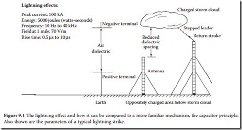
Natural phenomena of interest to facility managers consist mainly of lightning and related disturbances. The lightning effect can be compared to that of a capacitor, as shown in Figure 9.1. A charged cloud above the Earth will create an oppositely charged area below it of about the same size and shape. When the voltage difference is sufficient to break down the dielectric (air), the two “plates” of the “capacitor” will arc over and neutralize their respective charges. If the dielectric spacing is reduced, as in the case of a conductive steel structure (such as a transmitting tower), the arc-over will occur at a lower-than-normal potential and will travel through the conductive structure.
The typical duration of a lightning flash is approximately 0.5 s. A single flash is made up of various dis- charge components, among which are typically three or four high-current pulses called strokes. Each stroke lasts about one 1 ms; the separation between strokes is typically several tens of milliseconds. Lightning often appears to flicker because the human eye can just resolve the individual light pulses that are produced by each stroke.
Sources of Atmospheric Energy
Lightning is one of the more visible effects of atmospheric electricity. Stellar events that occurred light-years ago spray the earth and its atmosphere with atoms that have been stripped of most or all of their electrons. In the process of entering the atmosphere, these particles collide with air molecules, which are knocked apart, creating billions more ion pairs each second. Even though these ions may exist for only about 100 s, they constantly are being replenished from deep space. The existence of ions in the atmosphere is the funda- mental reason for atmospheric electricity. The primary sources of this energy are:
• Cosmic rays: Charged particles emitted by all radiating bodies in space. Most of these particles (ions) expend their energy in penetrating the envelope of air surrounding the earth. Through this process, they create more ions by colliding with air atoms and molecules. One high-energy particle may create up to a billion pairs of ions, many of which will become atmospheric electricity.
• Solar wind: Charged particles from the sun that continuously bombard the surface of the earth. Because about half of the earth’s surface is always exposed to the sun, variations are experienced from day to night. Solar wind particles travel at only 200 to 500 miles per second, compared with cosmic particles that travel at near the speed of light. Because of their slower speed, solar wind particles have less of an effect on air atoms and molecules.
• Natural radioactive decay: The natural disintegration of radioactive elements. In the process of radioactive decay, air molecules are ionized near the surface of the earth. One of the results is radon gas.
• Static electricity: Energy generated by the interaction of moving air and the earth.
• Electromagnetic generation: Energy generated by the movement of air molecules through the magnetic field of the earth.
The combined effects of cosmic rays and solar wind account for most atmospheric electrical energy.
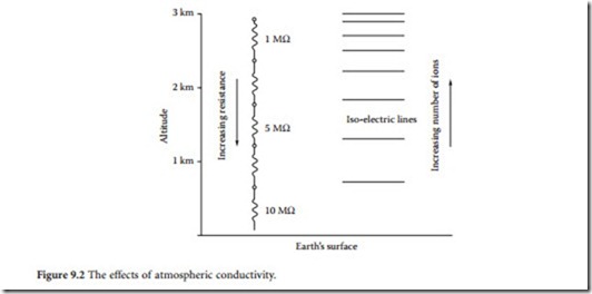
Atmospheric energy is present at all times, even during clear weather conditions. This energy takes the form of a voltage differential of 300 to 400 kV between the surface of the earth and the ionosphere. The voltage gradient is nonlinear; near the surface it may be 150 V/m of elevation, but it diminishes significantly at higher altitudes. Under normal conditions, the earth is negative with respect to the iono- sphere, and ions flow between the two entities. Because there are fewer free ions near the Earth than the ionosphere, the volts/meter value is thought to be greater because of the lower effective conductivity of the air. This concept is illustrated in Figure 9.2.
Thermodynamic activity in a developing storm cloud causes it to become a powerfully charged cell, usually negatively charged on the bottom and positively charged on the top. (See Figure 9.3.) This voltage difference causes a distortion in the voltage gradient, and in fact, the polarity inverts, with the earth becoming positive with reference to the bottom of the cloud. This voltage gradient increases to a high
decay curve is known as a reciprocal double exponential waveform. The trailing edge is the result of the resistance of the ionized channel depleting energy from the cloud. The path length for a lightning dis- charge is measured in kilometers. The most common source of lightning is cumulonimbus cloud forms, although other types of clouds (such as nimbostratus) occasionally can produce activity.
Although most lightning strikes are negative (the bottom of the cloud is negative with respect to the earth), positive strikes also can occur. Such strikes have been estimated to carry as much as 10 times the current of a negative strike. A positive flash can carry 200 kiloamps (kA) or more of discharge current. Such hot strikes, as they are called, can cause considerable damage. Hot strikes can occur in the winter and are often the aftereffect of a particularly active storm. After a number of discharges, the lower negative portion of the cloud will become depleted. When charged, the lower portion may have functioned as a screen or shield between the earth and the upper, positively charged portion of the cloud. When depleted, the shield is removed, exposing the earth to the massive charge in the upper cloud containing potentials of perhaps 500 MV or more.
Characteristics of Lightning
A typical lightning flash consists of a stepped leader that progresses toward the ground at a velocity that can exceed 50 m/μs. When sufficient potential difference between the cloud and the ground exists, arcs
move from the ground to the leader column, completing the ionized column from cloud to ground. A fast and bright return stroke then moves upward along the leader column at about one third the speed of light. Peak currents from such a lightning flash may exceed 100 kA, with a total charge as high as 100 coulombs (C). Although averages are difficult to assess where lightning is concerned, a characteristic flash exhibits a 2 μs rise time, and a 10 to 40 μs decay to a 50% level. The peak current will average 18 kA for the first impulse, and about half that for the second and third impulses. Three to four strokes per flash are common.
A lightning flash is a constant-current source. Once ionization occurs, the air becomes a conductive plasma reaching 60,000°F and becomes luminous. The resistance of an object struck by lightning is of small consequence except for the power dissipation on that object, which is equivalent to I 2R. Fifty per- cent of all strikes will have a first discharge of at least 18 kA, 10% will exceed 60 kA, and only 1% will exceed 120 kA.
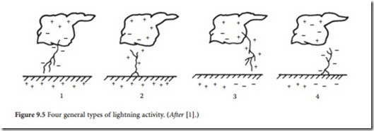
Four specific types of cloud-to-ground lightning have been identified. They are categorized in terms of the direction of motion (upward or downward) and the sign of the electric charge (positive or negative) of the initiating leader. The categories, illustrated in Figure 9.5, are defined as follows:
• Category 1: Negative leader cloud-to-ground discharge. By far the most common form of lightning, such discharges account for 90% or more of the cloud-to-ground flashes worldwide. Such events are initiated by a downward-moving negatively charged leader.
• Category 2: Positive leader ground-to-cloud discharge. This event begins with an upward-initiated flash from earth, generally from a mountaintop or tall steel structure. Category 2 discharges are relatively rare.
• Category 3: Positive leader cloud-to-ground discharge. Less than 10% of cloud-to-ground lightning worldwide is of this type. Positive discharges are initiated by leaders that do not exhibit the distinct steps of their negative counterparts. The largest recorded peak currents are in the 200 to 300 kA range.
• Category 4: Negative leader ground-to-cloud discharge. Relatively rare, this form of lightning begins with an upward leader that exhibits a negative charge. Similar to Category 2 discharges, Category 4 discharges occur primarily from a mountaintop or tall steel structure.
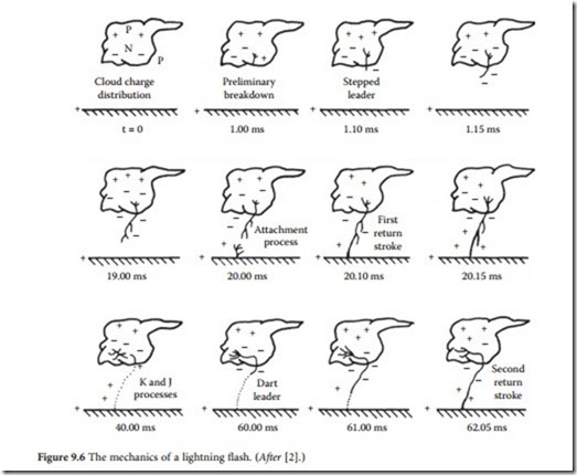
An idealized lightning flash is shown in Figure 9.6. The stepped leader initiates the first return stroke in a negative cloud-to-ground flash by propagating downward in a series of discrete steps, as shown. The breakdown process sets the stage for a negative charge to be lowered to the ground. A fully developed leader lowers 10 C or more of negative cloud charge to near the ground within a few tens of milliseconds. The average return leader current measures from 100 A to 1 kA. During its trip toward earth, the stepped leader branches in a downward direction, producing the characteristic lightning discharge.
The electrical potential difference between the bottom of the negatively charged leader channel and the earth can exhibit a magnitude in excess of 100 MV. As the leader tip nears ground level, the electric field at sharp objects on the ground increases until the breakdown strength of the atmosphere is exceeded. At that point, one or more upward-moving discharges are initiated, and the attachment process
begins. The leader channel is discharged when the first return stroke propagates up the previously ionized and charged leader path. This process will repeat if sufficient potential exists after the initial stroke. The time between successive strokes in a flash is usually several tens of milliseconds.
Cloud-to-Cloud Activity
A cloud discharge can be defined as any lightning event that does not connect with the earth. Most light- ning discharges occur within the confines of the cloud. Cloud discharges can be subdivided into intra- loud, intercloud, and cloud-to-air flashes. Although relatively insignificant insofar as earthbound equipment is concerned, current movement between clouds can create a corresponding earth current.
It is estimated that only about 10 to 25% of lightning occurs from cloud to ground; most discharges consist of intracloud activity. The reason is the enormous voltage difference that builds up between the top and bottom of a storm cloud. Furthermore, the region between the top and bottom of the cloud can be more highly ionized than the region between the bottom of the cloud and the earth. Currents developed by cloud-to-cloud discharges can induce significant voltages in conductors buried in-line with the charge movement. The windstorm effect also can induce voltages in above- or below-ground conductors as a result of rapid changes in the electrical potential of the atmosphere.
It is unnecessary, therefore, for atmospheric charge energy to actually strike a conductor of concern, such as a transmitting tower or utility company pole. In many cases, significant voltage transients can be generated solely by induction. Cloud-to-cloud charge movements generate horizontally polarized radiation, and cloud-to-ground discharges generate vertically polarized radiation. Field strengths exceeding 70 V/m can be induced in conductors a mile or so from a large strike.
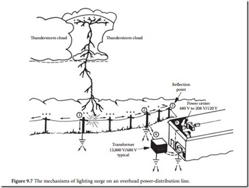
Figure 9.7 illustrates the mechanisms of lightning damage. Traveling waves of voltage and current follow all conductive paths until the flash energy has been dissipated. Reflections occur at discontinuities, such as lightning arresters (points 1, 2, 3, and 5) and transformers (points 4 and 6).
Lightning Protection
Research into the physical properties of lightning and related phenomena has two basic goals: (1) to iden- tify the character and severity of the threat, and (2) to devise methods to prevent damage resulting from atmospheric activity. Many different approaches have been taken over the years for controlling the dam- aging potential of lightning; some have become widely accepted, others remain controversial. The issue of lightning prevention clearly falls into the second category.
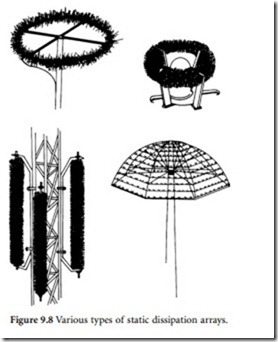
Application of the point discharge theory, the basis of lightning prevention schemes, is controversial to begin with. Still, it offers the promise of a solution to a serious problem faced by nearly all telecommunications operators. The goal is to dissipate static charges around a given structure at a rate sufficient to maintain the charge below the value at which a lightning flash will occur. The theory holds that discharge from the point of an electrode to a surrounding medium will follow predictable rules of behavior. The sharper the point, the greater the discharge. The greater the number of discharge points, the more effi- cient the dissipation system. Several static dissipators based on this theory are shown in Figure 9.8. Key design elements for such dissipators include:
• Radius of the dissipator electrode. The purpose of the dissipator is to create a high field intensity surrounding the device. Theory states that the electric field intensity will increase as the electrode radius is reduced. Dissipators, therefore, generally use the smallest-radius electrodes possible, con- sistent with structural integrity. There is, however, disagreement among certain dissipation-array manufacturers on this point. The optimum wire size, according to available literature, varies from 0.005-in.- to 1/8-in.-thick tapered spikes.
• Dissipator construction material. Important qualities include conductivity and durability. The dissipator should be a good conductor to provide: (1) the maximum discharge of current during normal operation, and (2) an efficient path for current flow in the event of a direct strike.
• Number of dissipator electrodes. Calculating the number of dissipator points is, again, the subject of some debate. However, because the goal of the system is to provide a low-resistance path to the atmosphere, it generally is assumed that the more discharge points, the more effec- tive the system. Dissipator electrode require- ments are determined by the type of structure being protected as well as the environmental features surrounding it.
• Density of dissipator electrodes. Experimenta- tion by some manufacturers has shown that the smaller the radius of the dissipator electrodes, the more closely they can be arranged without reducing the overall efficiency of the dissipator. Although this convention seems reasonable, disagreement exists among dissipation-array
manufacturers. Some say the points should be close together; others say they should be far apart.
• Configuration of the dissipator on the tower. Disagreement abounds on this point. One school of thought supports the concept of a dedicated “umbrella-type” structure at the top of the tower as the most efficient method of protecting against a lightning flash (Figure 9.9). Another view holds that the dissipator need not be at the highest point, and that it may be more effective if one or more dissipators are placed at natural dissipation points on the structure. Such points include side-mounted antennas and other sharp elements on the tower.
• Size and deployment of grounding electrodes. Some systems utilize an extensive ground system, others do not. One manufacturer specifies a collector composed of wire radials extending from the base of the tower and terminated by ground rods. Another manufacturer does not require a ground con- nection to the dissipator.
Available literature indicates that from 10 μA to 10 mA flow through a properly designed dissipative system into the surrounding air during a lightning storm. Figure 9.10 charts the discharge current recorded during a period of storm activity at a protected site. Although a lightning stroke can reach sev- eral hundreds of thousands of amperes, this energy flows for a very short period of time. The concept of the dissipative array is to continuously bleed off space charge current to prevent a direct hit.
Proof that static dissipators work as intended is elusive and depends upon the definition of “proof.” Empirical proof is difficult to obtain because successful performance of a static dissipator is evidenced by the absence of any results. Supporting evidence, both pro and con, is available from end-users of static dissipators, and from those who have studied this method of reducing the incidence of lightning strikes to a structure.
Protection Area
The placement of a tall structure over low-profile structures tends to protect the facilities near the ground from lightning flashes. The tall structure, typically a communications tower, is assumed to shield the facility below it from hits. This cone of protection is determined by the following:
• Height of the tall structure
• Height of the storm cloud above the earth
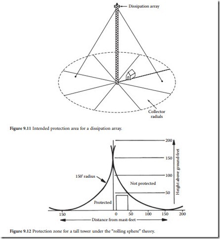
The higher the cloud, the larger the radius of the base of the protecting cone. The ratio of radius to base to height varies approximately from 1 to 2, as illustrated in Figure 9.11.
Conventional wisdom has held that a tower, whether protected with a static dissipation array or sim- ply a tower-top lightning rod, provided a cone of protection stretching out on all sides of the structure at an angle of about 45°. Although this theory held favor for many years, modifications have been proposed. One school of thought suggests that a smaller cone of perhaps 30° from the tower is more realistic. Another suggests that the cone theory is basically flawed and, instead, proposes a “rolling sphere” approach. This theory states that areas enclosed below a 150-ft rolling sphere will enjoy protection against lightning strikes. The concept is illustrated in Figure 9.12. Note that the top of the tower shown in
the figure is assumed to experience limited protection. The concept, as it applies to side-mounted antennas, is shown in Figure 9.13. The antenna is protected through the addition of two horizontally mounted lightning rods, one above the antenna and one below.
Electrostatic Discharge
A static charge is the result of an excess or deficiency of electrons on a given surface. The relative level of electron imbalance determines the static charge. Simply stated, a charge is generated by physical contact between, and then separation of, two materials. One surface loses electrons to the other. The types of materials involved, and the speed and duration of motion between the materials, determine the charge level. Electrostatic energy is a stationary charge phenomenon that can build up in either a nonconductive material or in an ungrounded conductive material. The charge can occur in one of two ways:
• Polarization: Charge buildup when a conductive material is exposed to a magnetic field.
• Triboelectric effects: Charge buildup that occurs when two surfaces contact and then separate, leaving one positively charged and the other negatively charged.
Friction between two materials increases the triboelectric charge by increasing the surface area that experiences contact. For example, a person accumulates charge by walking across a nylon carpet; discharge occurs when the person touches a conductive surface.
Triboelectric Effect
Different materials have differing potentials for charge. Nylon, human and animal hair, wool, and asbestos have high positive triboelectric potential. Silicon, polyurethane, rayon, and polyester have negative triboelectric potentials. Cotton, steel, paper, and wood all tend to be relatively neutral materials. The intensity of the triboelectric charge is inversely proportional to the relative humidity (RH). As humidity increases, electrostatic discharge (ESD) problems decrease. For example, a person walking across a carpet can generate a 1.5 kV charge at 90% RH, but will generate as much as 35 kV at 10% RH.
When a charged object comes in contact with another object, the electrostatic charge will attempt to find a path to ground, discharging into the contacted object. The current level is very low (typically less than 0.1 nA), but the voltage can be high (25 to 50 kV).
ESD also can collect on metallic furnishings, such as chairs and equipment racks. Sharp corners and edges, however, encourage a corona that tends to bleed the charge off
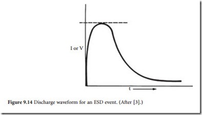
such objects. The maximum voltage normally expected for furniture-related ESD is about 6 to 8 kV. Because metallic fur- niture is much more conductive than humans, however, furni- ture-related ESD generally will result in higher peak discharge currents. Figure 9.14 shows a discharge waveform of a typical ESD event.
EMP Radiation
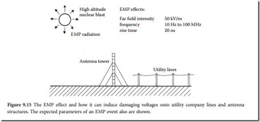
Electromagnetic pulse (EMP) radiation is the result of an intense release of electromagnetic waves that fol- lows a nuclear explosion. (See Figure 9.15.) The amount of damaging energy is a function of the altitude of detonation and the size of the device. A low-altitude or surface burst would generate a strong EMP, covering a few thousand square kilometers. However, the effects of the radiation would be meaningless, because the blast would destroy most structures in the area. A high-altitude burst, on the other hand, pre- sents a real threat to all types of communications and electronic systems. Such an explosion would gener- ate an EMP with a radius of more than 1000 km, a large portion of the U.S.
The sudden release of gamma rays in a nuclear explosion would cause almost instant ionization (the removal of electrons from atoms) of the atmospheric gases that surround the detonation area. Free electrons are driven outward. In a high-altitude event, the gamma rays travel great distances before ionizing the upper atmosphere. The forced movement of these electrons, which will again recombine with atoms in the atmosphere, creates a pulsed electromagnetic field.
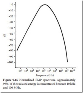
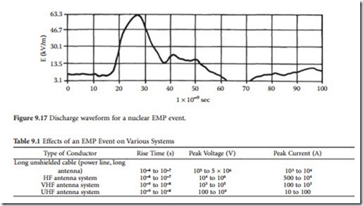
The amplitude and polarization of the field produced by a high-altitude detonation depends on the altitude of the burst, the yield of the device, and the orientation of the burst with respect to the receiving point. The EMP field creates a short but intense broadband radio frequency pulse with significant energy up to 100 MHz. Most of the radiated energy, however, is concentrated below 10 MHz. Fig- ure 9.16 shows the distribution of energy as a function of frequency. The electric field can be greater than 50 kV/m, with a rise time measured in the tens of nanoseconds. Figure 9.17 illustrates the field of a simulated EMP discharge.
Many times, lightning and other natural occurrences cause problems not because they
strike a given site, but because they strike part of the utility power system and are brought into the facility via the ac lines. Like- wise, damage that could result from EMP radiation would be most severe to equipment connected to the primary power source, because it is gener- ally the most exposed part of any facility. Table 9.1 lists the response of various systems to an EMP event.
Coupling Transient Energy
The utility power-distribution system can couple transient overvoltages into a customer’s load through induction or direct-charge injection. As stated previously, a lightning flash a mile away from a 12 kV line can create an electromagnetic field with a strength of 70 V/m or more. Given a sufficiently long line, substantial voltages can be coupled to the primary power system without a direct hit. Likewise, the field created by EMP radiation can be coupled to the primary power lines, but in this case at a much higher voltage (50 kV/m). Considering the layout of many parts of the utility company power system — long exposed lines over mountaintops and the like — the possibility of a direct lightning flash to one or more legs of the system is a distinct one.
Lightning is a point charge-injection process, with pulses moving away from the point of injection. The amount of total energy (voltage and current) and the rise and decay times of the energy seen at the load as a result of a lightning flash are functions of the distance between the flash and the load and the physical characteristics of the power-distribution system. Determining factors include:
• Wire size
• Number and sharpness of bends
• Types of transformers
• Types of insulators
• Placement of lightning suppressors
The character of a lightning flash covers a wide range of voltage, current, and rise-time parameters. Making an accurate estimate of the damage potential of a flash is difficult. A direct hit to a utility power line causes a high-voltage, high-current wave to travel away from the point of the hit in both directions along the power line. The waveshape is sawtooth in form, with a rise time measured in microseconds or nanoseconds. The pulse travels at nearly the speed of light until it encounters a significant change in line impedance. At this point, a portion of the wave is reflected back down the line in the direction from which it came. This action creates a standing wave containing the combined voltages of the two pulses. A high-energy wave of this type can reach a potential sufficient to arc over to another parallel line, a distance of about 8 ft on a local feeder (typically 12 kV) power pole.
