System Frequency Response
The electric frequency in a power system (system frequency, f) is a measure of the rotation speed of the synchronized generators. Changes in generation/demand will produce changes on the system frequency (speed of generators). System frequency is a continuously changing variable that is determined and controlled by the second- by-second (real time) balance between system demand and total generation.
A change in active power demand at one point of a network is reflected throughout the system by a change in electric frequency. Therefore, system frequency provides a useful index to indicate system generation and load imbalance.
Considering a system frequency disturbance condition (active power imbalance between generation and demand), the generator-demand dynamic relationship between the incremental mismatch power and the frequency can be expressed by an equivalent form of the swing equation. If demand is greater than generation, the frequency falls while if generation is greater than demand, the frequency rises.
The electrical devices connected to a synchronous power system are designed to operate at this system’s nominal frequency (f0), it is assumed to be 50 Hz as in the ENTSO-E Continental Europe system [11] (former UCTE) and UK [12].
Generally, deviations from this desired value arise due to imbalances between the instantaneous generation and consumption of electric power, which has an accelerating or decelerating effect on the synchronous machines. These small deviations on electric frequency are a normal result of stochastic variations in loads and should not affect the behavior of any component in the network. The electrical power system must be able to cope with those changes.
Frequency control is responsible for balancing real-time changes in load and generation that occur in a power system and ensuring that the frequency is approximately nominal throughout any period of time. The frequency control is responsible for helping to ensure frequency stability, which is defined as ‘‘the ability of a power system to maintain steady frequency following a severe system upset resulting in a significant imbalance between generation and load’’ [13]. Frequency stability analysis concentrates on studying the overall system stability for sudden changes in the generation-load balance (system frequency disturbance). In addition, the frequency control is responsible for limiting the frequency deviation that occurs after a large system frequency disturbance to the power balance in the system, e.g., the loss of a generator, the sudden disconnection of trans- mission line, as well as then returning the frequency to the nominal value within the required time. This task is accomplished using occasional frequency control services.
The SFR can be classified into two categories: Frequency Response (FR) Dynamic and Non Dynamic Frequency Response. The dynamic FR is continuously provided to manage the normal second by second changes on the system (i.e., small changes on demand). The nondynamic FR is usually a discrete service triggered at a defined frequency deviation.
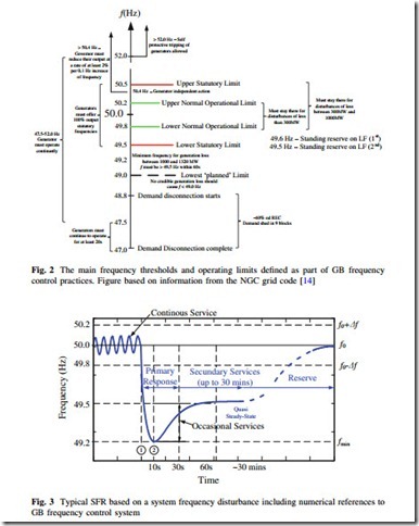
Frequency control practices differ significantly between the various transmission system operators in the world. Responsibility of frequency control is managed in GB by National Grid PLC [12], though the procurement and despatch of frequency response services, under normal operation conditions the frequency is maintained at f0 = 50 Hz within operational limits of ±0.2 Hz. In an abnormal event (instantaneous loss of 1,320 MW of generation), the maximum allowed system frequency deviation is Dfmax = -0.8 Hz. Figure 2 shows the main control thresholds and operational limits in terms of the absolute frequency magnitude that are used by National Grid (UK).
A representative example of the system frequency behavior following a frequency disturbance, (i.e., loss of generation or connection of a large load), is shown in Fig. 3. Numerical values depicted in Fig. 3 are related to the illustrative case of frequency control in GB.
Immediately after the disturbance, the system frequency starts dropping (region 1–2 of Fig. 3) at a rate mainly determined by the total inertia of the system (summation of the inertia constant of all generators and spinning loads). For occasions that the frequency drops greater than -0.20 Hz, some generating plants
are contracted to provide FR. The response is classified as an occasional service and has two parts: primary response and secondary response. Primary and secondary response are defined as the additional active power that can be delivered from a generating unit that is available at 10 and 30 s, respectively, after an event and that can be sustained for a further 20 s and 30 min respectively [14].
The primary response is provided by two mechanisms: Inertia response and Governor Action. The inertia response of fast primary response is related to a natural FR on synchronous generator. On an event of frequency reduction, the speed of synchronous generator also reduces and some of the kinetic energy stored in the rotating mass is released as an electrical energy. This is a very fast and natural response of synchronous generator directly connected to the grid and it is related to the rate of chance of frequency. A frequency controller named governor produces the governor action. An automatic droop control loop in governor acts on change in frequency and increases mechanical power on prime-mover to increase the generator output. This is a slower response and depends on main governor’s characteristic and time response of prime-mover.
The frequency control system consists of two main parts: the primary and secondary control. Tertiary control is additional and slower than primary and secondary frequency control.
The primary control refers to control actions that are done locally (on the power plant level) based on the set-points for frequency and power. The objective of the primary control is to maintain the balance between generation and load. This balance can be reached at post-disturbance steady-state frequency different from the nominal frequency (especially on governor including droop characteristic). The control task is shared by all generators participating in the primary frequency control irrespective of the location of the disturbance.
Following a system frequency disturbance, the system will not be able to return to the nominal frequency on its own, without additional action. The secondary frequency control, also called Load Frequency Control (LFC), adjusts power set points of the generators in order to compensate for the remaining frequency error after the primary control has acted. The purpose of secondary control actions is to restore the system frequency to the nominal set point and ensure that any tie-line flows in the system are at their contracted level. LFC can also be performed manually as in the Nordel powers system, the ENTSO-E Continental Europe interconnected system, an automatic scheme is used, which can also be called Automatic Generation Control (AGC).
The tertiary control acts after the system frequency has been returned to, or very near to, the nominal value. The task of tertiary control depends on the organizational structure of a given power system and the role that power plants play in this structure [15]. It is different to primary and secondary control because it does not deal directly with controlling the frequency. It is not discussed here.
Following a large system frequency disturbance (e.g., large generation loss), a power system’s frequency may drop quickly if the remaining generation no longer matches the load demand. Significant loss of generating the plant without adequate system response can produce extreme frequency excursions outside the working range of plant. Depending on the size of the frequency deviation experienced, emergency control and protection schemes may be required to maintain power system frequency.
If the frequency control system cannot restore the system frequency and the power system operators may follow an emergency control plan such as under- frequency load shedding (UFLS). UFLS is a widely used last resort against large low frequency events that may cause cascading outages and even the disconnection of parts of a system. The UFLS strategy is designed to rapidly balance the demand of electricity with the supply and to avoid a rapidly cascading power system failure. Allowing normal frequency variations within expanded limits will require the coordination of primary control and scheduled reserves with generator load set points [16]; for example under-frequency generation trip (UFGT), over- frequency generation trips (OFGT), or over-frequency generator shedding (OFGS) and other frequency-controlled protection devices.
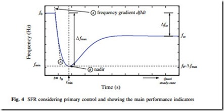
Several performance indicators may be used to describe and to evaluate the FR. Figure 4 shows a typical and idealistic SFR (secondary and tertiary controls are not included) where the main performance indicators are depicted:
(i) Maximum frequency gradient ([df/dt]max) as observed by ROCOF (Rate-Of- Change-Of-Frequency) relays (line A).
(ii) Maximum frequency deviation (fmax) as observed by under-frequency relays (point B) is defined as the absolute frequency deviation from nominal fre- quency (f0).
Both these quantities shall be kept as small as possible to prevent relays from tripping df/dt.
(iii) Frequency nadir (fmin) measures the minimum post contingency frequency (point B).
(iv) Frequency nadir time (tmin) is the time it takes for the response to reach its nadir.
(v) Quasi-steady-state deviation (Dfss) is the deviation between the nominal frequency value and the final value. The term ‘‘quasi’’ is used because a steady-state analysis is performed on a dynamical system. Though, the dynamics considered are slow enough to allow such a definition. The quasi- steady state is usually defined with the help of a maximum gradient that the frequency should not exceed.
Mainly by the following aspects defines the magnitude of the dynamic maxi- mum frequency deviation (Dfmax) in a classical power system:
(i) The amplitude and development over time of the system frequency disturbance.
(ii) The kinetic energy of rotating machines in the system.
(iii) The number of generators subject to primary control and primary control reserve and how it is between these generators.
(iv) The dynamic characteristics of the machines (including controllers).
(v) The dynamic characteristics of loads, particularly the self-regulating effect of loads.
The quasi-steady-state frequency deviation is governed by the amplitude of the disturbance and the network power-frequency characteristic, which is influenced mainly by the following aspects:
(i) The droop characteristic included on all generators subject to primary frequency control in the synchronous area.
(ii) The sensitivity of power demand consumption to variations in system frequency.

