Lubrication system
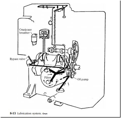
The first order of business should be the lubrication system. To check it out you must have a reasonably good notion of the oiling circuits. Figure 8-13 is a
drawing of the Onan DJ series lubrication system. The crankcase breather is included because it has much to do with oil control. Should it clog, the engine will leak at every pore. Oil passes from the screened pickup tube (suspended in the pan) to the pump, which sends it through the filter. From there the filtered oil is distributed to the camshaft, the main bearings (and through rifle-drilled holes in the crankshaft to the rod bearings and wrist pin), and to the valve gear. Valve and rocker arm lubrication is done through a typically Onan “showerhead” tube. Tiny holes are drilled in the line and deliver an oil spray at about 25 psi. On its return to the sump, the oil dribbles down the push rods to lubricate the cam lobes and tappets.
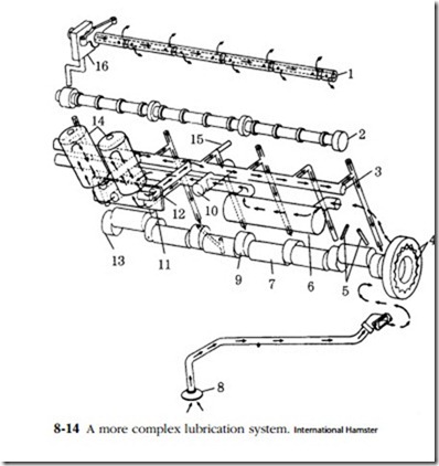
The system in Fig. 8-14 is employed in six-cylinder engines. From the bottom of the drawing, oil enters the pickup tube, then goes to the Gerotor pump. Unlike most oil pumps, this one is mounted on the end of the crankshaft and turns at engine speed. The front engine cover incorporates inlet and pump discharge ports. Oil is sent through a remote cooler (6), then directed back to the block, where it exits again to the filter bank (11). Normally oil passes through these filters. However, if the filters clog or if the oil is thick from cold, a pressure differential type of bypass valve (12) opens and allows unfiltered flow.
The main oil gallery (3) distributes the flow throughout the engine. Some goes to the main bearings and through the drilled crankshaft to the rods. The camshaft
bearings receive oil from the same passages that feed the mains. The rearmost cam journal is grooved. Oil passes along this groove and up to the rocker arms through the hollow rocker shaft. On its return this oil lubricates the valve stems, pushrod ball sockets, tappets, and cam lobes. Other makes employ similar circuits, often with a geared pump.
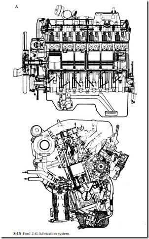
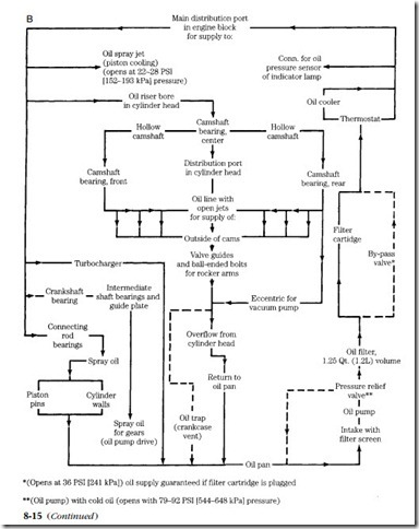
Figure 8-15 describes the Ford 2.3L lubrication system, which is surprisingly sophisticated for a small and, by diesel standards, inexpensive product. Pressurized oil goes first to the filter, described in the following section.
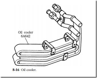
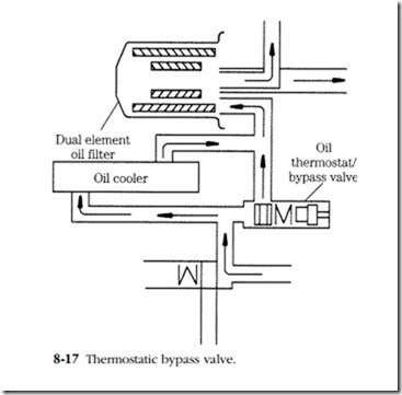
Depending on oil temperature, output from the filter goes either directly to the main distribution gallery or to the gallery by way of an oil cooler (Fig. 8-16). A ther- mostatic valve, located in the filter housing, directs the flow (Fig. 8-17). Cooling the oil during cold starts is counterproductive, and the valve remains closed; as oil tem- perature increases, the valve extends to split the flow between the gallery and cooler. At approximately 94°C, all flow is diverted to the cooler. As a safety measure, the bypass valve opens if cooler pressure drop exceeds 14 psi. Thus, a stoppage will not shut down oil flow, although long-term survivability is compromised.
Camshaft lubrication, a weak point on many ohc engines, shows evidence of careful attention. A large-diameter riser, feeding from the main gallery, supplies oil to the center camshaft bearing. At that point the flow splits, part of it entering the hollow camshaft and part of it going to an overhead spray bar. The camshaft acts as an oil gallery for the remaining two shaft bearings; the spray bar provides lubrica- tion for camshaft lobes, rockers, and valve tips.
The main bearings are lubricated through rifle-drilled ports connecting the webs and main gallery. As a common practice, diagonal ports drilled in the crankshaft convey oil from the webs to adjacent crankpins. Spray jets, again fed by the main gallery, cool the undersides of the pistons and provide oil for the piston pins. A gear and crescent pump—the lightest, most compact type available—supplies the necessary pressure.
This cursory examination of the oil circuitry on three very different engines should underscore the need to come to terms with these systems. No other system has such immediate implications for the integrity of the mechanic’s work.
Clogging is the most frequent complaint, caused by failure to change oil and filters at proscribed intervals, and abetted by design flaws. Expect to find total or par- tial blockage wherever the oil flow abruptly changes direction or loses velocity. Prime candidates are the cylinder head/block interface, spray jets, and the junctions between cross-drilled passages. Neither immersion-type chemicals, heat, nor com- pressed air can be depended on to remove metal chips and sludge. Drilled passages must be cleared by hand, using riflebore brushes and solvent.
Thorough cleaning is never more important than after catastrophic failure, which releases a flood of metallic debris into the oiling system. In this case, the oil cooler can present a special problem. Modern, high-density coolers do not respond well to chemical cleaners and frustrate even the most flexible swabs. A new or used part— whose history is known—is sometimes the only solution.
Leaks can develop at the welch (expansion) plugs or, less often, at the pipe plugs that blank off cross-drilled holes and core cavities. It is also possible for cracks to open around lifter bores and other thin-section areas. A careful mechanic
will discard welch plugs (after determining that spares are available!) and apply fresh sealant to pipe plug threads during a rebuild. Most oil-wetted cracks can be detected visually.
Internal leaks that have been missed will show when the system is filled with pressurized oil before start-up.
