DC switchgear
Technology and applications
The most obvious difficulty in interrupting dc current is that there is no natural current zero. The current has to be forced to zero by the circuit breaker by generating an arc voltage across the break contacts which is greater than the system voltage. Since the load and the fault current is highly inductive the circuit breaker interrupting device must be capable of dissipating all the energy in the circuit until arc extinction.
Until the early 1970s the main method of arc extinction was to stretch and cool the arc in an arcing chamber under the influence of the magnetic field produced by a series connected magnetic blow-out coil. A voltage drop in dc arcs of about 1 V/mm has typically been accepted, and although this is dependent on arcing conditions, it is evident that for any system voltage above a few hundred volts the arc must be fairly long. This is fairly difficult to achieve, and it promotes the chance of the arc re-striking to other components within the switchgear.
The uses for dc switchgear include generator field control, deep mine winding gear and superconducting toroidal coils, but by far the most common requirement is in urban transit systems where dc supplies are ideally suited for light to medium power requirements. The majority of systems operate on supply voltages ranging from 650 V to 1500 V with a few inter-city routes using 3000 V.
Urban dc rail systems can be categorized as rapid transit systems or light rail systems. An underground or suburban railway generally using large rolling stock such as the London Underground is typically described as a rapid transit system. Such systems require high normal current, high fault-rated dc circuit breakers because of the large load currents drawn on start-up of the rolling stock and the low impedance of the track power supply connections. In order to limit the let-through current during a fault, and thereby protect the ac/dc conversion equipment, high-speed dc circuit breakers are nearly always specified for this type of system. Typical ratings for use in rapid transit systems are 750 V, 6000 A rectifier circuit breakers and 4000 A track feeder circuit breakers with a maximum fault interrupting rating of 125 kA at 900 V.
A light rail system is typically a tram system, with or without track, using an over- head catenary–pantograph supply. Switchgear ratings are lower with typical ratings of 750 V, 2000 A for rectifier breakers and 1250 A for track feeder breakers, with a maximum fault interrupt rating of 50 kA, 900 V. The circuit breakers used are generally defined as semi-high speed.
Semiconductor circuit breakers
Semiconductors have been considered as a potential advance in the field of dc circuit breakers for many years. The speed of operation far exceeds the capability of conventional mechanical circuit breakers and if the short-circuit current can be detected rapidly a semiconductor circuit breaker could be capable of switching the circuit in fractions of a millisecond. This would limit the let-through fault current to a smaller value with less possibility of damage to equipment. Semiconductor switches are capable of interrupting large short circuit currents on traction dc power supplies, but they are unable alone to absorb and dissipate all the fault energy.
One method involves a forced commutation circuit in parallel with the semiconductor, providing a low impedance path into which the fault current is temporarily diverted. This creates a current zero in the semiconductor switch circuit allowing it to turn off. Other methods such as series-resonant commutation can be used but in each case the high reverse voltage caused by rapid turn off of a highly inductive circuit must be limited, otherwise dc equipment will be damaged. This can be achieved using a surge arrester or capacitor within the circuit breaker to absorb the energy or by circulating the energy around the fault circuit using a free-wheel diode.
Semiconductor circuit breakers are not widely used for three main reasons:
● high forward conduction losses due to forward volt drop of the semiconductor junction and the high current requirement of dc circuit breakers
● isolation when the circuit breaker is switched off is reliant upon semiconductor dielectric strength
● the limitation to the speed of operation is the detection time of the protection device. It is not possible to devise a protection relay that can operate rapidly enough to reap the full benefits of the semiconductor switch and to reliably discriminate between all types of evolving faults and normal transient load conditions.
The use of a mechanical switch in parallel with the semiconductor eliminates the forward conduction loss and a series isolating switch operating after fault clearance
provides a physical isolation distance. However, in order to achieve the benefit of high-speed fault clearance the mechanical components have to be capable of closing and opening in a few hundred microseconds. The result is a more complex and expensive switch in parallel with a sophisticated and complex electronic device that will not normally compete with a conventional circuit breaker.
Air circuit breakers
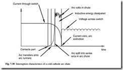
The cold cathode arc chute is the preferred method of arc interruption in modern dc circuit breakers. It is ideally suited to the interruption of dc since it provides a fairly fixed arc voltage irrespective of the arc current. The cold cathode arc chutes are arranged as shown in Fig. 7.29 and the current and voltage characteristics of an interruption can be seen in Fig. 7.30. An arc is formed as the contacts part and at this stage the voltage across that arc will be very low, in the order of tens of volts. This is dependent on arcing current, method of arc movement, contact separation and contact materials. The arc then moves towards the splitter plates along the arc runners, being stretched as it moves and generating an arc voltage of a few hundred volts and it is then split into the series arcs by the splitter plates when a sharp jump in the arc voltage can be seen. The difference between the arc voltage forced in the arc chute and the system voltage describes the arcing time within plates.
There are a number of techniques that are used to force the arc into the splitter plates. By careful arrangement of the contact and runner system it is possible to generate a tight current loop which, by its nature, forces the arc into a larger loop. This however does not provide strong enough magnetic fields at the lower currents to move the arc column away from the contact area. A mechanical puffer driven from the opening mechanism is one technique that is used to move the arc column away from
the contact area, applying a blast of air between the contacts. This is independent of arcing current but it adds complexity and is only available for a short period of time.
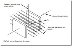
A magnetic field orthogonal to the arc is an effective method to move the arc rapidly from the contact gap into the splitter plates and this has been successfully used on many ac and dc air circuit breakers. The magnetic field can be generated by permanent magnets, secondary coils or by the current itself. If the circuit breaker is to interrupt current in both directions, it can be seen in Fig. 7.31 that the field must be reversible in order to have the same resultant force upwards on the arc and with secondary coils or permanent magnets, it can be difficult to reverse the field especially
at low currents. Connecting secondary coils across the contact gap gives the correct field orientation of field, but these have to be switched after the arc has been extinguished and this can lead to problems in isolation. Using the main current to provide the field inherently gives the correct orientation of force on the arc, but in order to develop a uniform field with a high enough flux density across the contacts it is necessary to link the flux from several turns of main conductor. This can be cumbersome because of the large-sectional copper required for the relatively high rated currents of the switch.
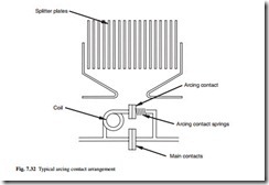
Often arcing contacts are used to solve this problem. The main contacts carry normal current and part slightly earlier than the arcing contacts, so they can be made from a less arc-resistant material, which reduces the heat generated in the switch under normal operating conditions. This also enables the addition of a coil in the arcing contact arrangement, as shown in Fig. 7.32, providing a magnetic field across the contacts. It is imperative that the main contacts break earlier than the arcing contacts even when the arcing contacts are badly worn, and that the inductance of the coil is very low to assist in current transfer to the arcing contacts with dI/dt values of potentially tens of thousands of amps per millisecond.
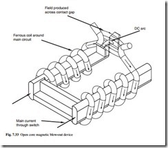
Another method now in use is to link the flux from the main current with a ferrous coil or open core around the main current. The open-core magnetic blow-out shown in Fig. 7.33 provides a magnetic field in the correct orientation while the main current is flowing, with enough flux linkage to interrupt dc arcs at very low currents. The avoidance of large coils carrying the main current allows for a very compact passive device with no moving parts that has been proven to work over the full range of duties required.
Without assistance from a device such as the open-core magnetic blow-out, the arc may not transfer into the arc chute at low currents (up to 200 A) as its magnetic field
would be insufficient to force it off the contacts. At very low currents (in the order of tens of amperes, depending upon contact gap, system voltage, contact material, circuit time constant etc.) the arc can be extinguished across the contact gap without transferring onto the runners and into the chute. Critical currents can occur on some circuit breakers when the current is too small to transfer correctly into the chute and too large to be interrupted across either the contacts or on the arc runners. The result can be very long and inconsistent arcing times or in the worst case failure to interrupt. The position becomes worse when the circuit breaker is required to interrupt a current in its critical area in the reverse direction following the clearance of a relatively large current in the forward direction. The forward current interruption can magnetize the steel plates in the arc chute (and possibly other mechanism components) and the remanent magnetic field in the arc chute is then in the opposite direction to that required to draw the arc into the chute in the reverse direction. If the reverse current is small the magnetic field cannot be reversed and the arc cannot be interrupted.
A type test is specified in the BSEN 50123-2 standard to search for forward and reverse critical currents. These are defined as the current for which the particular circuit breaker has the longest arcing time. These low currents are inductive and cover the range for which it is most likely that air circuit breakers will have difficulty interrupting. The specification also calls for a reverse test at the forward critical current after a large forward interruption.
DC traction fault duties
DC circuit breakers are classified according to their characteristics during fault interruption. Some common requirements are highlighted in the circuit breaker designations:
● very high speed current limiting circuit breakers, V
● high speed current limiting circuit breakers, H
● semi-high speed circuit breakers, S
Type V and type H circuit breakers are also described as current-limiting circuit breakers because they have a break time which is sufficiently short to prevent the short- circuit current reaching the peak value it would have attained without interruption. Very high speed circuit breakers have a break time no greater than 4 ms, irrespective of other parameters of the circuit. This speed of operation is limited to semiconductor circuit breakers and hybrid circuit breakers that are a combination of semiconductor and mechanical switches. High speed circuit breakers have an opening time no greater than 5 ms and a total break time not greater than 20 ms when the current to be interrupted has a sustained value of at least 7 times the circuit breaker setting and dI/dt is greater than or equal to 5 kA/ms. Type S circuit breakers provide assured current interruption, but current limitation may not take place. The circuit breaker in most common use is the type H because of its ability to operate quickly and limit damaging let-through fault current at an affordable price.
The specification of the circuit breaker type is decided by the fault levels the system can generate, and the types of fault are characterized by their location in the traction system.
The functions for which the dc circuit breaker can be used within a standard traction system are:
● interconnector circuit breaker, I (also called bus-section or section circuit breaker)
● line feeder circuit breaker, L
● rectifier circuit breaker, R
These can have different requirements, and current interruption direction can also be specified, as well as direct-acting overload release direction. It can be advantageous for discrimination purposes to specify the direction in which the release operates, to ensure that only the breaker feeding a fault opens and that supply is maintained elsewhere. Current interruption in both directions is necessary unless it can be shown that there are no circumstances under which a circuit breaker can be opened when the current is flowing in an opposite direction.
DC traction protection
The power supplied through the switchgear fluctuates as trains start, accelerate and regenerate, and one or more trains can be travelling or transferring onto different sections of track. To discriminate between a fault and such a variety of load conditions requires a sophisticated and well co-ordinated protection system. Depending upon the point in the system at which the fault occurs, it is quite common for the magnitude of the current to be less than that flowing due to the traction load.
While short-circuit currents on the dc traction supply can be large and damaging to equipment on the dc supply, the value of the short-circuit current on the ac supply due to dc faults could be fairly small. Also, ac switchgear protection operating and fault clearance times may be too long to protect the ac/dc conversion equipment effectively. The dc circuit breakers and the protection system must therefore be fast-operating. Electronic and/or electromagnetic protection relays are always used on modern dc switchboards, the current being sensed by a shunt or other transducer and the circuit breaker being tripped by the shunt trip coil. As the last line of defence, it is common practice to specify a high-set direct acting instantaneous series overcurrent release within the circuit breaker.
In order to minimize the risk of an undetected fault condition the following types of protection have been developed.
● Direct-acting overcurrent protection: This is incorporated into the circuit breaker, the device directly tripping the breaker through a mechanical linkage or magnetic circuit. The purpose is to provide protection for overload conditions and high-speed operation under high-current faults. In most networks the device will not provide discrimination between normal load conditions and low level or distant faults. Line feeder and rectifier circuit breakers utilise this form of protection.
● Rate of rise protection (dI/dt): This is now the most commonly used software- driven protection system in traction applications. As it measures the rate of rise of current through the switchgear it is able to react rapidly during the initial increase of current at the on-set of a fault before the current reaches a large, damaging value. When properly developed it is effective in discriminating between distant faults and normal train starting and accelerating currents, but a detailed knowledge of the system is imperative for correct setting of the relay. The settings are chosen to ensure that the device will not trip on the most severe train starting condition but will trip under distant fault conditions. An extension of this principle is DELTA I (∆I) protection, in which the initial dI/dt triggers a current measurement. After a set time, the change in current is measured and if it exceeds the set value (determined from the most onerous train starting current) a trip is issued. The dI/dt setting can be lower than that for standard rate of rise protection, offering better sensitivity for distant fault detection. In addi- tion the time delay setting can be reduced to give more sensitive protection for less distant faults.
● Undervoltage protection: Relays can be used to monitor a reduced track voltage under fault or load conditions at the substation and at points in between. The sys- tem may be used for both single and double-end fed systems, pilot wires being used to trip the appropriate circuit breaker or breakers. In order to provide dis- crimination and to allow circuit breakers to be closed onto tracks at a reduced voltage, undervoltage protection system needs to incorporate a time delay. This must be of the order of 100 ms, which renders this type of protection inadequate for close-up faults. As the system measures only voltage it cannot be used to provide directional discrimination.
● Falling-voltage impedance protection: Impedance protection is an extension of the falling-voltage principle in which track current is also monitored. The impedance of a track section seen from the circuit breaker is the ratio of track voltage to the current flowing through the circuit breaker. An impedance value, normally equal to the loop impedance of the whole track section provides the setting value. The presence of a fault closer to the substation will lead to the V/I being reduced and if it falls below the set impedance value, a trip command can be issued. This system is used extensively by Network Rail in the UK and on systems utilizing additional switching stations located between the rectifier substations.
● Instantaneous overcurrent: This offers the same protection as circuit breaker direct-acting overload protection, but since modern digital relays can be used to give more accurate and faster tripping times, it may assist in the scheme co-ordination. Like direct-acting overload protection it must always be set above the level required during trains starting and accelerating and therefore it can not always detect distant faults.
Safety features and interlocking
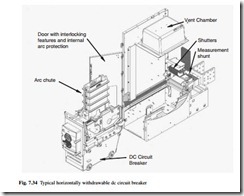
Modern dc switchgear is almost exclusively of the horizontally withdrawable type to facilitate full isolation, maintenance and testing. Figure 7.34 shows a modern withdrawable dc circuit breaker, cutaway to show the shutter and venting arrangement. It is important that interlocks prevent an incorrect sequence of actions from causing unsafe operation. The circuit breaker compartment usually caters for two positions, a test/isolated position, and a service position. The circuit breaker can be operated in either mode through the secondary control and auxiliary connections. The interlocking principles should follow the following philosophy:
● When the circuit breaker is inserted into the cubicle, the earth connection is made before all other connections. This earth connection should be suitably rated for the system earth fault current.
● The circuit breaker can be operated in the test position, and must remain isolated from the primary circuit.
● The main compartment door must be closed before the circuit breaker moves from the isolated to the service position.
● The shutters should not be operated by the circuit breaker mechanism while the door is open, and are independent in operation.
● The door cannot be opened once the circuit breaker has been moved from the isolated position.
● The circuit breaker cannot be moved from isolated or service position until it is open.
● If the auxiliary connections are not made, there will be no possibility of unsafe operation when the breaker is put into the service position.
Applicable standards and testing
Until relatively recently it was the case that most dc network operators would purchase their electrical equipment with only limited third party test evidence. Indeed it was not unusual for equipment either to be put into trial service on the railway or for entire test tracks to be constructed. Such trial work with equipment is extremely expensive and can be disruptive to the operation of the railway network as a whole, and most testing of dc switchgear now takes place at high power testing laboratories using various synthetic test duties to simulate railway conditions.
Testing or specifying equipment can be a difficult task because of the numerous variations between railway network requirements and manufactured equipment, and most customers and manufacturers normally use the various national and international standards that specify dc switchgear, shown in Table 7.7. Of the standards currently in use the EN 50123:2003 series (also known as IEC 61992) and ANSI C37.16-2000 are commonly quoted, the EN series being the more up to date and complete.
The EN 50123 series requires that dc switchgear is subjected to a series of tests which normally includes a range of short circuit duties, electrical endurance testing,
temperature rise testing, dielectric testing, ingress protection and mechanical endurance testing. Each duty or type of test is subject to variation depending on the type of circuit breaker to be tested, the system voltage and the characteristics of the circuit that is being switched. In particular a considerable amount of testing is undertaken to assess performance under the various fault conditions that may arise at low or reverse currents.
From an operator’s perspective, testing at maximum energy levels is particularly important because the test can be used to simulate extended electrical endurance causing considerable wear to both the circuit breaker contacts and arc chute.
As with much railway equipment dc switchgear is typically located in remote locations of restricted size, requiring special consideration of mechanical reliability and effect of temperature rise within the equipment. Circuit breakers can be subjected to extended mechanical endurance tests of over 50 000 operations without any maintenance, often including variations in temperature, humidity and control system voltage. Temperature rise testing is normally undertaken on complete switchgear assemblies with conditions as close to those in service as possible, particularly if ventilation is restricted. Such testing sometimes includes operator-defined overload cycles to simulate the effects of increased numbers of trains on the railway.

