Voltage (Potential) Transformers
VTs are designed for connecting line-to-line or line-to-neutral. The purpose of the VT is to provide an isolated secondary voltage that is an exact
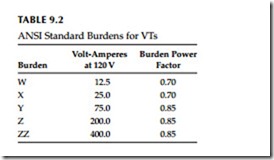
 proportionate representation of primary voltage. However, transformers draw core-magnetizing current from the primary circuit, and a constant error results independent of the burden connected to it. Also, variable error results due to load or burden current flowing through the effective imped- ance of the transformer. The total error is the sum of these two errors under any burden condition. The ANSI standard C57.13-1993(R2003) lists the clas- sification of VTs encountered in service as W, X, Y, Z, and ZZ. The standard burden designations are shown in Table 9.2 for these VTs.
Accuracy classes are based on the requirement that the TCF be within speci- fied limits when the power factor of the metered load is between 0.6 and 1.0 lagging for a specified burden and at voltages from 90% to 110% of rated trans- former voltage. The ANSI accuracy classes for VTs are shown in Table 9.3.
The ratings of VTs encompass the following:
• Insulation class and basic impulse level
• Rated primary voltage and ratio
• Accuracy ratings at standard burdens
• Thermal burden, that is, the maximum burden the transformer can carry at rated secondary voltage without exceeding its temperature rise, above 30°C ambient
VTs are designed for connecting line-to-line or line-to-neutral. The purpose of the VT is to provide an isolated secondary voltage that is an exact
proportionate representation of primary voltage. However, transformers draw core-magnetizing current from the primary circuit, and a constant error results independent of the burden connected to it. Also, variable error results due to load or burden current flowing through the effective imped- ance of the transformer. The total error is the sum of these two errors under any burden condition. The ANSI standard C57.13-1993(R2003) lists the clas- sification of VTs encountered in service as W, X, Y, Z, and ZZ. The standard burden designations are shown in Table 9.2 for these VTs.
Accuracy classes are based on the requirement that the TCF be within speci- fied limits when the power factor of the metered load is between 0.6 and 1.0 lagging for a specified burden and at voltages from 90% to 110% of rated trans- former voltage. The ANSI accuracy classes for VTs are shown in Table 9.3.
The ratings of VTs encompass the following:
• Insulation class and basic impulse level
• Rated primary voltage and ratio
• Accuracy ratings at standard burdens
• Thermal burden, that is, the maximum burden the transformer can carry at rated secondary voltage without exceeding its temperature rise, above 30°C ambient
