Construction
Figure 9-6 illustrates an air-cooled Ishikawajima-Harima turbocharger of the type found on engines in the 100–150-hp range. The inset shows the water-cooled version of the same turbocharger, plumbed into the engine cooling system. All modern small-engine turbochargers follow these general patterns.
Floating bushings, located in the central bearing chamber, support the shaft. These bushings, like the connecting rod bearings specified for the original Ford V-8, float on the ID and OD. Thus, bushing speed is half that of shaft speed, which is to say that the bushings can reach speeds of 60,000 or 70,000 rpm. A floating thrust bushing contains axial motion.
Also note the way the impeller wheels cantilever from the bushings, so that the masses of the rotating assembly are concentrated near the ends of the shaft. This “dumb-bell” configuration requires precise wheel balance and extremely accurate shaft alignment.
The bearing section is lubricated and cooled by engine oil, generally routed through external pipes or hoses. Shaft seals keep oil from entering the turbine and compressor sections.
The turbocharger is usually the last component to receive oil pressure and might continue to rotate after the engine stops. To ensure an adequate oil supply to the bearings, operators should idle the engine for at least 30 seconds upon starting and for the same period before shutdown.
Wastegate
All turbocharger installations incorporate some form of boost limitation; other- wise, boost would rise with load until the engine destroyed itself.
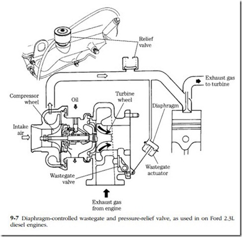
Turbocharger geometry, sometimes abetted by inlet restrictions and designed-in exhaust backpressure, limit boost on constant-speed engines. Automotive and light truck engines have surplus turbocharging capability for boost at part throttle. These applications employ a wastegate—a kind of flap valve—that automatically opens at a preset level of boost to shunt exhaust gas around the turbine.
Most wastegates are controlled by a diaphragm, open to the atmosphere on one side and to manifold pressure on the other (Fig. 9-7). The Ford unit shown also incorporates a relief valve. Normally the wastegate opens at 10.7 psi; should it fail to do so, the relief valve opens at 14 psi and, because it is quite noisy, alerts the driver to the overboost condition.
Other wastegates are spring-loaded and usually include an adjustment, appro- priately known as the “horsepower screw.” As usually configured, tightening the screw increases available boost. Therefore, exercise restraint.
Test wastegate operation by loading the engine while monitoring rpm and mani- fold pressure. If the installation does not include a boost gauge, connect a 0–20 psi pressure gauge at any point downstream of the compressor. The diaphragm-sensing line (on units so-equipped) serves as a convenient gauge point. Note, however, that the gauge must be connected with a tee fitting to keep the wastegate functional. High gear acceleration from 2500 rpm or so should generate sufficient load to open the gate.
The control philosophy discussed in the preceding paragraphs implies that the turbocharger is used for power enhancement. When mid-range torque is the object,
the wastegate opens early, at the engine speed corresponding to peak torque out- put. Most of these applications employ computer-controlled wastegates, whose response is conditioned by manifold pressure, engine rpm, coolant temperature, and other variables. No generalized test procedure has been developed for these devices.
Aftercoolers
Compressing air raises its temperature, which reduces change density and tends to defeat the purpose of supercharging. Sophisticated turbocharger installations include a heat exchanger, or aftercooler, between the compressor outlet and intake manifold. The cooling medium can be air, engine coolant, or—for marine applications—water. The plate and tube seawater-fed aftercooler used with the Yanmar 4LH-HTE boosts out- put to 135 hp, or 30 hp more than an identical engine without aftercooling.
Air-cooled heat exchangers work most efficiently when mounted in front of the radiator. Engine coolant should be taken off at the pump discharge and returned to some point low on the water jacket.
Air-cooled units require little attention, other than an occasional dust off. Liquid- cooled heat exchangers should be cleaned as needed to remove scale and fouling, and periodically tested by blowing low-pressure (25-psi maximum) air through the tubes. Water intrusion into the intake tract can be expensive.
Routine maintenance
The first priority is to obtain actual performance data, particularly with reference to turbocharger behavior. The full story would require a dynamometer to extract, but one can gain useful insight by observing the changes in manifold pressure under working loads that, at some point in the test, should be great enough to cause the wastegate to open. The rise in oil temperature and variations in crankcase pressure supply additional parts of the picture.
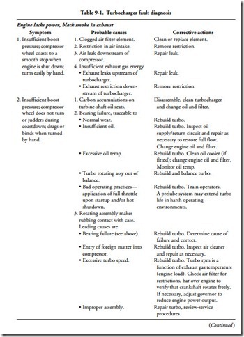
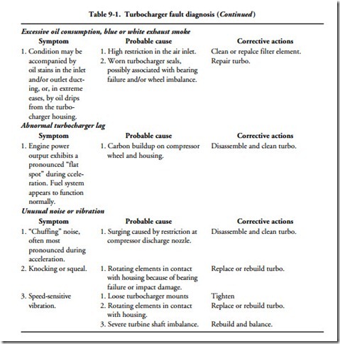
Do not operate a turbocharged engine unless the air cleaner (or spark arrestor) is in place and the intake-side ducting secure. The compressor acts as a vacuum cleaner, drawing in foreign, objects which will severely damage the unit and might cause it to explode. The troubleshooting chart (Table 9-1) makes reference to coast-down speed. If you feel it is necessary to observe compressor rotation, cover the turbocharger inlet with a screen to at least keep fingers and other large objects out of the mechanism.
When dismantling a turbocharger and related hardware, make a careful tally of all fasteners, lockwashers, and small parts removed. Be absolutely certain that all are accounted for before starting the engine. Immediately shut down the engine if the turbocharger makes unusual noise or vibrates.
Turbocharging (and supercharging generally) put severe stress on lubrication, air inlet, crankcase ventilation, and exhaust systems.
Lubrication system
Elevated combustion pressure contaminates the oil with blowby gases and pro- motes oxidation by raising crankcase oil temperature. That fraction of the oil diverted to the turbocharger can undergo 80°F temperature rise in its passage over the bushings. Change lube oil and filter(s) frequently.
The cost and disposal problems associated with filters make reusable filters attractive for fleet operators. Racor, a division of Parker Hannifin, manufactures a series of liquid filters with washable, stainless-steel elements and a TattleTale light that alerts the operator when the filter needs to be cleaned.
Frequently inspect the turbocharger and its oiling circuitry for evidence of leaks that, if neglected, can draw down the crankcase.
Air inlet system
Dust particles, entering through a poorly maintained filter or through leaks in the ducting rapidly erode the compressor wheel. Leaks downstream of the com- pressor cost engine power and waste fuel.
Crankcase ventilation system
This system removes combustion residues and, in the process, subjects the crankcase to a slight vacuum. In normal operation, fresh air enters through the breather filter and crankcase vapors discharge to the atmosphere (prepollution engines) or to the
Under severe load, blowby gases accumulate faster than they can be vented and escape through the breather filter. These flow reversals, which occur more frequently in turbocharged engines, tend to clog the filter. Restrictions at the filter allow corro- sive gases to linger in the crankcase. A partially functional filter can also pressurize the crankcase under the severe blowby conditions that accompany heavy loads. Oil seals and gaskets leak as a consequence.
Under light loads, reduced flow through the breather depressurizes the crankcase. Low crankcase pressures encourage oil to migrate into the turbocharger and collect in the aftercooler on engines with positive crankcase ventilation. Because oil is a fairly good thermal insulator, the efficiency of the aftercooler suffers. Tests of a Detroit Diesel engine, conducted by Diesel Research, Inc., established that oil migration resulting from a 40% efficient breather cost 6% of engine output. The engine in question had 4000 hours on the clock.
Exhaust system
Restrictions downstream of the turbine—crimped pipes, abrupt changes in direction, clogged mufflers—reduce turbo efficiency and, in extreme cases, represent enough load to induce boost. However, exhaust leaks between the engine and turbocharger are more typical. The pipe rusts out (especially if wrapped in insulation), fatigues, or cracks under the 1000°F-plus temperature. If OEM parts do not give satisfactory service, you might try calling a Flexonics applications engineer (312-837-1811). The company makes a line of exhaust tubing, fitted with metal bellows to absorb thermal expansion.
Turbocharger inspection
The seven-step inspection procedure outlined here was adapted, with modifi- cations, from material supplied by John Deere.
1. Turbo housing Before disconnecting the oil lines, examine external surfaces of the housing for oil leaks, which would almost certainly mean turbo seal failure.
2. Compressor housing inlet and wheel Inspect the compressor wheel for ero- sion and impact damage. Erosion comes about because of dust intrusion; impact damage is prima facie evidence of negligence. Carefully examine the housing ID and compressor blade tips for evidence of rubbing contact, which means bearing failure.
3. Compressor housing outlet Check the compressor outlet for dirt, oil, and carbon accumulations. Dirt points to a filtration failure; oil suggests seal fail- ure, although other possibilities exist, such as clogged turbo-oil return line or crankcase breather. Carbon on the compressor wheel might suggest some sort of combustion abnormality, but the phenomenon is also seen on healthy engines. I can only speculate about the cause.
4. Turbine housing inlet Inspect the inlet ports for oil, heavy carbon deposits, and erosion. Any of these symptoms suggest an engine malfunction.
5. Turbine housing outlet and wheel Examine the blades for impact damage.
Look for evidence of rubbing contact between the turbine wheel and the housing, which would indicate bearing failure.
6. Oil return port The shaft is visible on most turbochargers from the oil return port. Excessive bluing or coking suggests lubrication failure, quite possibly caused by hot shutdowns.
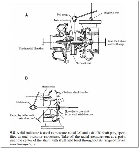
7. Bearing play measurements Experienced mechanics determine bearing condi- tion by feel, but use of a dial indicator gives more reliable results. Note that mea- surement of radial, or side-to-side, bearing clearance involves moving the shaft from one travel extreme to another, 180° away (Fig. 9-8A). Hold the shaft level during this operation, because a rocking motion would muddy the results. Axial motion is measured as travel between shaft thrust faces (Fig. 9-8B). In very gen- eral terms, subject to correction by factory data for the unit in question, we would be comfortable with 0.002 in. radial and 0.003 in. axial play. Note that Schwitzer and small foreign types tend to be set up tighter.
Overhaul
Only the most general instructions can be provided here, because construction details, wear limits, and torque specifications vary between make and model. It should also be remarked that American mechanics do not, as a rule, attempt tur- bocharger repairs. The defective unit is simply exchanged for another one.
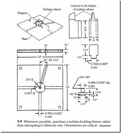
However, there are no mysteries or secret rites associated with turbocharger work. Armed with the necessary documentation and the one indispensable special tool—a turbine-shaft holding fixture—any mechanic can replace the bearings and seals, which is what the usual field overhaul amounts to.
The holding fixture secures the integral turbine wheel and shaft during removal and installation of the compressor nut. Figure 9-9 illustrates plans for one such fixture, used on several Detroit Diesel applications. Dimensions vary, of course, with tur- bocharger make and model.
Factory-supplied documentation should alert you to any peculiarities of the instrument, such as a left-handed compressor-nut thread or the need to heat the compressor wheel prior for removal. Special precautions include the following:
• Do not use a wire wheel or any other sort of metallic tool on turbo wheels or shaft. Remove carbon deposits with a soft plastic scraper and one of the various solvents sold for this purpose. Light scratches left by wheel contact on the turbo housings can be polished out with an abrasive.
• Do not expose the turbine shaft to bending forces of any magnitude. Pull the shaft straight out of its bearings. Use a double u-joint between the socket and the wrench when removing and torquing the compressor-wheel nut.
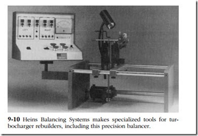
• Do send out the rotating assembly for shaft alignment and balancing (Fig. 9-10).
• Do exercise extreme cleanliness during all phases of the operation.
• Do prelubricate the bearings with motor oil and prefill the bearing housing prior to starting the engine.
• Do make certain that all fasteners and small tools are accounted for and not lurking within the turbocharger or its plumbing.
