Introduction
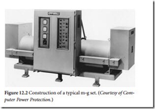
As the name implies, a motor-generator (m-g) set consists of a motor powered by the ac utility supply that is mechanically tied to a generator, which feeds the load. (See Figure 12.1.) Transients on the utility line will have no effect on the load when this arrangement is used. Adding a flywheel to the motor-to-generator shaft will protect against brief power dips (up to 0.5 s on many models). Figure 12.2 shows the construction of a typical m-g set. The attributes of an m-g include the following:
• An independently generated source of voltage can be regulated without interaction with line-voltage changes on the power source. Utility line changes of ±20% commonly can be held to within ±1% at the load.
• The rotational speed and inertial momentum of the rotating mass represents a substantial amount of stored rotational energy, preventing sudden changes in voltage output when the input is momentarily interrupted.
• The input and output windings are separated electrically, preventing transient disturbances from propa- gating from the utility company ac line to the load.
• Stable electrical characteristics for the load: (1) output voltage and frequency regulation, (2) ideal sine wave output, and (3) true 120° phase shift for three-phase models.
• Reduced problems relating to the power factor presented to the utility company power source.
The efficiency of a typical m-g ranges from 65 to 89%, depending on the size of the unit and the load. Motor-generator sets have been used widely to supply 415 Hz power to mainframe computers that require this frequency.
System Configuration
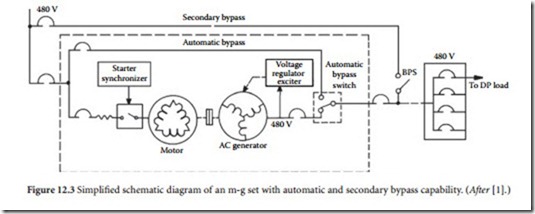
There are a number of types of motor-generator sets, each having its own characteristics, advantages, and disadvantages. A simplified schematic diagram of an m-g is shown in Figure 12.3. The type of motor that drives the set is an important design element. Direct-current motor drives can be controlled in speed inde- pendently of the frequency of the ac power source from which the dc is derived. Use of a dc motor thereby gives the m-g set the capability to produce power at the desired output frequency, regardless of variations in input frequency. The requirement for rectifier conversion hardware, control equipment, and commutator maintenance are drawbacks to this approach that must be considered.
The simplest and least-expensive approach to rotary power conditioning involves the use of an induction motor as the mechanical source. Unfortunately, the rotor of an induction motor turns slightly slower than the rotating field produced by the power source. This results in the generator being unable to produce 60 Hz output power if the motor is operated at 60 Hz and the machines are directly coupled end-to-end at their shafts, or are belted in a 1:1 ratio. Furthermore, the shaft speed and output frequency of the generator decreases as the load on the generator is increased. This potential for varying output frequency may be acceptable where the m-g set is used solely as the input to a power supply in which the ac is rectified and converted to dc. However, certain loads cannot tolerate frequency changes greater than 1 Hz/s and frequency deviations of more than 0.5 Hz from the nominal 60 Hz value.
Low-slip induction motor-driven generators are available that can produce
59.7 Hz at full load, assuming 60 Hz input. During power interruptions, the output frequency will drop further, depending upon the length of the inter- ruption. The capability of the induction motor to restart after a momentary power interruption is valuable. Various systems of variable-speed belts have been tried successfully. Magnetically controlled slip- ping clutches have been found to be largely unsatisfactory. Other approaches to make the induction motor drive the load at constant speed have produced mixed results.
Using a synchronous motor with direct coupling or a cogged 1:1 ratio belt drive guarantees that the output frequency will be equal to the motor input frequency. Although the synchronous motor is more expensive, it is more efficient and can be adjusted to provide a unity PF load to the ac source. The starting characteristics and the mechanical disturbance following a short line-voltage interruption depend, to a large extent, on motor design. Many synchronous motors that are not required to start under load have weak starting torque and may use a pony motor to aid in starting. This approach is shown in Figure 12.4.
Those motors designed to start with a load have starting pole face windings that provide starting torque comparable to that of an induction motor. Such motors can be brought into synchronism while under load with proper selection of the motor and automatic starter system. Typical utility company ac inter- ruptions are a minimum of six cycles (0.1 s). Depending upon the design and size of the flywheel used, the ride-through period can be as much as 0.5 s or more. The generator will continue to produce output power for a longer duration, but the frequency and rate of frequency change will most likely fall outside of the acceptable range of most DP loads after 0.5 s.
If input power is interrupted and does not return before the output voltage and frequency begin to fall outside acceptable limits, the generator output controller can be programmed to disconnect the load. Before this event, a warning signal is sent to the DP control circuitry to warn of impending shutdown and to initiate an orderly interruption of active computer programs. This facilitates easy restart of the computer after the power interruption has passed.
It is important for users to accurately estimate the length of time that the m-g set will continue to deliver acceptable power without input to the motor from the utility company. This data facilitates accu- rate power-fail shutdown routines. It is also important to ensure that the m-g system can handle the return of power without operating overcurrent protection devices because of high inrush currents that may be required to accelerate and synchronize the motor with the line frequency. Protection against the latter problem requires proper programming of the synchronous motor controller to correctly disconnect and then reconnect the field current supply. It may be worthwhile to delay an impending shutdown for 100 ms or so. This would give the computer time to prepare for the event through an orderly interruption. It also would be useful if the computer were able to resume operation without shutdown, in case utility power returns within the ride-through period. Control signals from the m-g controller should be configured to identify these conditions and events to the DP system.
Generators typically used in m-g sets have substantially higher internal impedance than equivalent kVA-rated transformers. Because of this situation, m-g sets sometimes are supplied with an oversized generator that will be lightly loaded, coupled with a smaller motor that is adequate to drive the actual load. This approach reduces the initial cost of the system, decreases losses in the motor, and provides a lower operating impedance for the load.
Motor-generator sets can be configured for either horizontal installation, as shown previously, or for vertical installation, as illustrated in Figure 12.5.
The most common utility supply voltage used to drive the input of an m-g set is 480 V. The genera- tor output for systems rated at about 75 kVA or less is typically 208 Y/120 V. For larger DP systems, the most economical generator output is typically 480 V. A 480 to 208 Y/120 V three-phase isolating trans- former usually is included to provide 208 Y/120 V power to the computer equipment.
Motor Design Considerations
Both synchronous and induction motors have been used successfully to drive m-g sets, and each has advantages and disadvantages. The major advantage of the synchronous motor is that while running
normally, it is synchronized with the supply frequency. An 1800 rpm motor rotates at exactly 1800 rpm for a supply frequency of exactly 60 Hz. The generator output, therefore, will be exactly 60 Hz. Utility fre- quencies average 60 Hz; utilities vary the frequency slowly to maintain this average value under changing load conditions. Research has shown that utility operating frequencies typically vary from 58.7 to 60.7 Hz. Although frequency tolerances permitted by most computer manufacturers are usually given as ±0.5 Hz on a nominal 60 Hz system, these utility variations are spread over a 24-hour period or longer and generally do not result in problems for the load.
The major disadvantage of a synchronous motor is that the device is difficult to start. A synchronous motor must be started and brought up to pull-in speed by an auxiliary winding on the armature, known as the armortisseur winding. The pull-in speed is the minimum speed (close to synchronous speed) at which the motor will pull into synchronization if excitation is applied to the field. The armortisseur winding is usually a squirrel-cage design, although it may be of the wound-rotor type in some cases. This winding allows the synchronous motor to start and come up to speed as an induction motor. When pull- in speed is achieved, automatic sensing equipment applies field excitation, and the motor locks in and runs as a synchronous machine. As discussed previously, some large synchronous motors are brought up to speed by an auxiliary pony motor.
The armortisseur winding can produce only limited torque, so synchronous motors usually are brought up to speed without a load. This requirement presents no problem for DP systems upon initial startup. However, in the event of a momentary power outage, problems can develop. When the utility ac fails, the synchronous motor must be disconnected from the input immediately, or it will act as a genera- tor and feed power back into the line, thus rapidly depleting its stored (kinetic) rotational energy. During a power failure, the speed of the motor rapidly drops below the pull-in speed, and when the ac supply returns, the armortisseur winding must reaccelerate the motor under load until the field can be applied again. This requires a large winding and a sophisticated control system. When the speed of the m-g set is below synchronous operation, the generator output frequency may be too low for proper computer operation.
The induction motor has no startup problems, but it does have slip. To produce torque, the rotor must rotate at slightly lower speed than the stator field. For a nominal 1800 rpm motor, the actual speed will be about 1750 rpm, varying slightly with the load and the applied input voltage. This represents a slip of about 2.8%. The generator, if driven directly or on a common shaft, will have an output frequency of about 58.3 Hz. This is below the minimum permissible operating frequency for most computer hard- ware. Special precision-built low-slip induction motors are available with a slip of approximately 0.5% at a nominal motor voltage of 480 V. With 0.5% slip, speed at full load will be about 1791 rpm, and the directly driven or common-shaft generator will have an output frequency of 59.7 Hz. This frequency is within tolerance, but close to the minimum permissible frequency.
A belt-and-pulley system adjustable-speed drive is a common solution to this problem. By making the pulley on the motor slightly larger in diameter than the pulley on the generator (with the actual diameters adjustable) the generator can be driven at synchronous speed.
Voltage sags have no effect on the output frequency of a synchronous motor-driven m-g set until the voltage gets so low that the torque is reduced to a point at which the machine pulls out of synchroniza- tion. Resynchronization then becomes a problem. On an induction motor, when the voltage sags, slip increases and the machine slows down. The result is a drop in generator output frequency. The adjust- able-speed drive between an induction motor and the generator solves the problem for separate machines. If severe voltage sags are anticipated at a site, the system can be set so that nominal input volt- age from the utility company produces a frequency of 60.5 Hz, 0.5 Hz on the high side of nominal fre- quency. Figure 12.6 charts frequency vs. motor voltage for three operating conditions:
• Slip compensation set high (curve A)
• Slip compensation set for 60 Hz (curve B)
• No slip compensation (curve C)
Through proper adjustment of slip compensation, considerable input-voltage margins can be achieved.
Single-Shaft Systems
There are two basic m-g set machine mechanical designs used for DP applications: (1) separate motor- generator systems, and (2) single-shaft, single-housing units. Both designs can use either a synchronous or induction motor. In each case, there are advantages and disadvantages. The separate machine design (discussed previously) uses a motor driving a physically separate generator by means of a coupling shaft or pulley. In an effort to improve efficiency and reduce costs, manufacturers also have produced various types of single-shaft systems.
The basic concept of a single-shaft system is to combine the motor and generator elements into a single unit. A common stator eliminates a number of individual components, making the machine less expensive to produce and mechanically more efficient. The common-stator set substantially reduces mechanical energy losses associated with traditional m-g designs, and it improves system reliability, as well. In one design, the stator is constructed so that alternate slots are wound with input and output
windings. When it is fed with a three-phase supply, a rotating magnetic field is created, causing the dc- excited rotor to spin at a synchronous speed. By controlling the electrical characteristics of the rotor, control of the output at the secondary stator windings is accomplished.
Common-stator machines offer lower working impedance for the load than a comparable two- machine system. For example, a typical 400 kVA machine has approximately an 800 kVA frame size. The larger frame size yields a relatively low-impedance power source capable of clearing subcircuit fuses under fault conditions. The output of the unit typically can supply up to seven times the full-load current under fault conditions. Despite the increase in frame size, the set is smaller and lighter than comparable systems because of the reduced number of mechanical parts.
Flywheel Considerations
In an effort to achieve higher energy and power densities, m-g set designers have devoted considerable attention to the flywheel element itself. New composite materials and power electronics technologies have resulted in compact flywheel “batteries” capable of high linear velocity at the outside radius of the flywheel (tip speed) [2]. The rotational speed of the flywheel is important because the stored energy in a flywheel is proportional to the square of its rotational speed. Therefore, an obvious method for maximiz- ing stored energy is to increase the speed of the flywheel. All practical designs, however, have a limiting speed, which is determined by the stresses developed within the wheel resulting from inertial loads. These loads are also proportional to the square of rotational speed. Flywheels built of composite materials weigh less and, hence, develop lower inertial loads at a given speed. In addition, composites are often stronger than conventional engineering metals, such as steel. This combination of high strength and low weight enables extremely high tip speeds, relative to conventional wheels.
For a given geometry, the limiting energy density (energy per unit mass) of a flywheel is proportional to the ratio of material strength to weight density, otherwise known as the specific strength. Table 12.1 illustrates the advantage that composite materials offer in this respect.
Recent advances in composite materials technology may allow nearly an order of magnitude advan- tage in the specific strength of composites when compared to even the best common engineering metals. The result of this continuous research in composites has been flywheels capable of operation at rotational speeds in excess of 100,000 rpm, with tip speeds in excess of 1000 m/s.
These high speeds bring with them new challenges. The ultrahigh rotational speeds that are required to store significant kinetic energy in these systems virtually rule out the use of conventional mechanical bearings. Instead, most systems run on magnetic bearings. This relatively recent innovation uses mag- netic forces to levitate a rotor, eliminating the frictional losses inherent in rolling element and fluid film bearings. Unfortunately, aerodynamic drag losses force most high-speed flywheels to operate in a partial vacuum, which complicates the task of dissipating the heat generated by ohmic losses in the bearing electromagnets and rotor. In addition, active magnetic bearings are inherently unstable and require sophisticated control systems to maintain proper levitation.
The integrated generator of these systems is usually a rotating-field design, with the magnetic field supplied by rare-earth permanent magnets. Because the specific strength of these magnets is typically just fractions of that of the composite flywheel, they must spin at much lower tip speeds; in other words, they must be placed very near the hub of the flywheel. This compromises the power density of the generator.
An alternative is to mount them closer to the outer radius of the wheel, but contain their inertial loads with the composite wheel itself. Obviously, this forces the designer to either derate the machine speed or operate closer to the stress limits of the system.
Maintenance Considerations
Because m-g sets require some maintenance that necessitates shutdown, most systems provide bypass capability so the maintenance work can be performed without having to take the computer out of service. If the automatic bypass contactor, solid-state switch, and control hardware are in the same cabinet as other devices that also need to be de-energized for maintenance, a secondary bypass is recommended. After the automatic bypass path has been established, transfer switching to the secondary bypass can be enabled, taking the m-g set and its automatic bypass system out of the circuit completely. Some auto- matic bypass control arrangements are designed to transfer the load of the generator to the bypass route with minimum disturbance. This requires the generator output to be synchronized with the bypass power before closing the switch and opening the generator output breaker. However, with the load taken off the generator, bypass power no longer will be synchronized with it. Consequently, retransfer of the load back to the generator may occur with some disturbance. Adjustment for minimum disturbance in either direction requires a compromise in phase settings, or a means to shift the phase before and after the transfer.
The use of rotating field exciters has eliminated the need for slip rings in most m-g designs. Brush inspection and replacement, therefore, are no longer needed. However, as with any rotating machinery, bearings must be inspected and periodically replaced.
Motor-Generator UPS
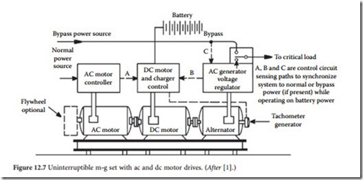
Critical DP applications that cannot tolerate even brief ac power interruptions can use the m-g set as the basis for an uninterruptible source of power through the addition of a battery-backed dc motor to the line-driven ac motor shaft. This concept is illustrated in Figure 12.7. The ac motor normally supplies power to drive the system from the utility company line. The shafts of the three devices all are interconnected, as shown in the figure. When ac power is present, the dc motor serves as a generator to charge the
battery bank. When line voltage is interrupted, the dc motor is powered by the batteries. Figure 12.8 shows a modified version of this basic m-g UPS using only a dc motor as the mechanical power source. This configuration eliminates the inefficiency involved in having two motors in the system. Power from the utility source is rectified to provide energy for the dc motor, plus power for charging the batteries. A complex control system to switch the ac motor off and the dc motor on in the event of a utility power fail- ure is not needed in this design.
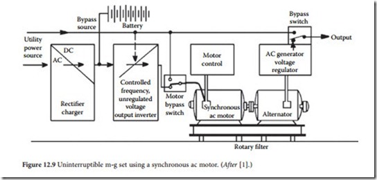
The m-g UPS also can be built around a synchronous ac motor, as illustrated in Figure 12.9. Utility ac energy is rectified and used to drive an inverter, which provides a regulated frequency source to power the synchronous motor. The output from the dc-to-ac inverter need not be a well-formed sine wave, or a well-regulated source. The output from the generator will provide a well-regulated sine wave for the load. The m-g set also can be operated in a bypass mode that eliminates the rectifier, batteries, and inverter from the current path, operating the synchronous motor directly from the ac line.
An m-g UPS set using a common-stator machine is illustrated in Figure 12.10. A feedback control circuit adjusts the firing angle of the inverter to compensate for changes in input power. This concept is taken a step further in the system shown in Figure 12.11. A solid-state inverter bypass switch is added to improve efficiency. During normal operation, the bypass route is enabled, eliminating losses across the
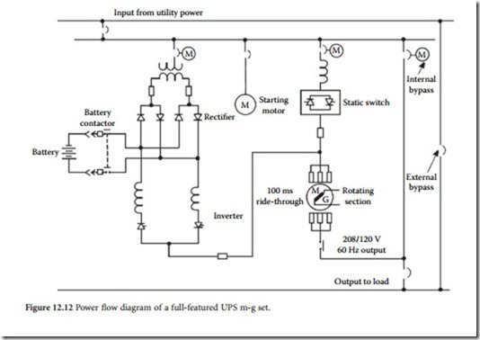
rectifier diodes. When the control circuitry senses a drop in utility voltage, the inverter is switched on, and the bypass switch is deactivated. A simplified installation diagram of the inverter/bypass system is shown in Figure 12.12. Magnetic circuit breakers and chokes are included as shown. An isolation trans- former is inserted between the utility input and the rectifier bank. The static inverter is an inherently simple design; commutation is achieved via the windings. Six thyristors are used. Under normal operating conditions, 95% of the ac power passes through the static switch; 5% passes through the inverter. This arrangement affords maximum efficiency, while keeping the battery bank charged and the rectifiers and inverter thyristors preheated. Preheating extends the life of the components by reducing the extent of thermal cycling that occurs when the load suddenly switches to the battery backup supply. The static switch allows for fast disconnect of the input ac when the utility power fails.
Kinetic Battery Storage System
As outlined previously, one of the parameters that limits the ride-through period of an m-g set is the speed decay of the flywheel/generator combination. As the flywheel slows down, the output frequency
drops. This limits the useful ride-through period to 0.5 s or so. Figure 12.13 shows an ingenious modification of the classic power conditioning template that extends the potential ride-through considerably. As shown in the figure, an m-g set is used in a UPS-based system as an element of the dc supply grid. The major components of the system include:
• Steel flywheel for energy storage
• Small drive motor, sized at 15 to 20% of the rated system output, to start the flywheel and maintain its normal operating speed
• Variable speed drive (VSD) to slowly ramp the flywheel up to speed and maintain it at the desired rpm
• Generator to convert the kinetic energy stored in the flywheel into electrical energy
• Diode bridge rectifier to convert the ac generator output to dc for use by the UPS bus, which continues to draw usable energy essentially independent of flywheel rpm
Because the ac output of the generator is converted to dc, frequency is no longer a limiting factor, which allows the dc voltage output to be maintained over a much greater range of the flywheel’s rpm envelope.
In operation, the small drive motor spins the flywheel while the variable speed drive maintains the proper motor speed [4]. Because the amount of stored kinetic energy increases by the square of the fly- wheel rpm, it is possible to greatly increase stored energy, and thus ride-through, by widening the fly- wheel’s usable energy output range. These factors permit typical ride-through times from 10 s to several minutes, depending on loading and other operating conditions. The benefits of this approach include the reduced cycling of battery supplies and engine-generator systems.
Related posts:
Incoming search terms:
- motor generator set circuit diagram
- motor generator
- motor generator set diagram
- control panel of motor generator set diagram
- m g set diagram
- motor generator diagram
- describe the testing of motor generator set with diagram
- mg set
- Control panel of motor generator set
- Draw the free hand sketches of control panel of motor generator set
- mg set connection diagram
- Motor generator set with diagram
- motor generator set panel diagram
- mg set diagram
- layout arrangement of dc generator and motor control panel
- diagram of control panel of motor generator
- layout arrangement of dc generator motor
- Mg set ac to d c circuit diagram with stater image
- ंग सेट कंट्रोल पैनल डायग्राम
- m g set disgram
- starting running building up voltage and loading of motor generator mg set
- mg set practical
- M-G s
- diagram of synchronous motor with induction pony motor starting
- motor genrator diagram
- Draw the layout arrangement of D C Generator and motor control panel
- motor generate set with diagram
- flywheel generator design
- mg set dighram
- control panel motor generator set diagram
- dc motor generator diagram
- circuit diagram of a motor generator set
- phase ac from the fiywheel motor generator to a
- motor generator set
- MG set control panel diagra
- draw the layout arrangement of dc generator and motor control panel diagram
- dc to ac mg set circuit diagram with starter connection
- dc motor generator (diagram)
- dc motor generator set
- working diagram of mg set
- dicribe the motor generator set and diagram
- drawing the layout arrangement of D C m g set control panel
- what is the efficiency of motor generator set
- connection of mg set
- power generator mail
- Connection diagrame Ac to dc MG SET
- motor generator set ac to dc circuit diagram panal
- mg set pannel bord digram
- mg set connection
- Full diagram of Motor generator set

