Fuses and protection relays
Protection and co-ordination
Fuse and protection relays are specialized devices for ensuring the safety of personnel working with electrical systems and for preventing damage due to various types of faults. Common applications include protection against overcurrents, short circuits, overvoltage and undervoltage.
The main hazard arising from sustained overcurrent is damage to conductors, equipment or the source of supply by overheating, possibly leading to fire. A short circuit may melt a conductor, resulting in arcing and the possibility of fire; the high electromechanical forces associated with a short circuit also cause mechanical stresses which can result in severe damage. A heavy short circuit may also cause an explosion. Rapid disconnection of overcurrents and short circuits is therefore vital. An important parameter in the design and selection of protective devices is the prospective current; this is the current which would flow at a particular point in an electrical system if a short circuit of negligible impedance were applied. The prospective current can be deter- mined by calculation if the system impedance or fault capacity at that point is known.
In addition, personnel working with electrical equipment and systems must be protected from electric shock. A shock hazard exists when a dangerous voltage difference is sustained between two exposed conducting surfaces which could be touched simultaneously by different parts of the body. This voltage normally arises between earth and metalwork which is unexpectedly made live and if contact is made between the two through the body, a current to earth is caused. Fuses can provide protection where there is a low-resistance path to earth, because a high current flows and blows the fuse rapidly. To detect a wide range of currents flowing to earth it is necessary to use current transformers and core-balance systems; these operate a protective device, such as a circuit breaker such as the rcd described in section 7.3.4 for low-voltage systems.
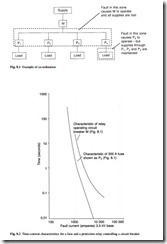
When designing an electrical protection system it is also necessary to consider co-ordination so that when a fault occurs, the minimum section of the system around the fault is disconnected. This is particularly important where disconnection has safety implications, for instance in a hospital. An illustration of co-ordination is shown in Fig. 8.1.
Protective devices are described by a time–current characteristic. In order to achieve co-ordination between protective devices, their time–current characteristics must be sufficiently separated, as shown in Fig. 8.2, so that a fault downstream of
both of them operates only the device nearest to the fault. A variety of shapes of time–current characteristic for both fuses and protection relays are available for different applications.
Another consideration when designing electrical protection is back-up. In some circuits it is desirable to have a device, such as an mcb (see section 7.3.3) which disconnects lower overcurrents and can be reset. Higher overcurrents, which the mcb cannot disconnect without being damaged, are disconnected by an upstream fuse in series with the mcb. This arrangement has the advantage that re-closure onto a severe fault is less likely, because replacement of the fuse would be necessary in this case as well as re-closure of the mcb. It is also possible for a protective device to fail, for example because of mishandling. The effects of a failure can be minimized or avoided by a back-up protective device which operates under such conditions. In Fig. 8.1, protective device M backs up each of the protective devices P. However, if M operates as a back-up device, co-ordination is lost because all four branches of the circuit lose supply, not just the faulty branch.
