Other Insulation Test Methods
DC voltage testing has been used extensively for high-capacitance current load such as machine windings and high-voltage cables. However, the stress distribution imposed by DC voltage does not stress the insulation system the same as does the AC voltage test. Field testing with AC voltage requires substantially large test equipment (because of the capacitive charging requirements), which is impractical. Therefore, the need for new test methods has led to the development of the one-tenth hertz test and resonant test methods for testing large machines with AC voltage. These two methods are described briefly next.
10.12.1 Very Low Frequency Testing
This test is a variation of the 60 Hz AC high-potential test and is referred to as “one-tenth hertz” or very low frequency (VLF) Testing. It utilizes a very
low frequency, such as 0.1 Hz voltage for searching flaws in the insulation system similar to that of 60 Hz test voltage equipment. The equipment, how- ever, is considerably lighter and easier to handle. By using 0.1 Hz instead of 60 Hz voltage, the size (kVA) of test equipment is reduced by a ratio of 1:600. This is because the capacitive charging current is 1/600 of the current needed at power (60 Hz) frequency. Current VLF test equipment is cost-effective and reasonably portable. Experience with VLF testing indicates that the voltage stress distribution across the groundwall insulation is similar to the power frequency. Therefore, the VLF testing has the same advantages as that of the power frequency AC high-potential testing. The recommended test value for maintenance and acceptance testing is 1.15 times the 60 Hz test value to achieve an equal searching effect, that is, 1.15 (1.3E + 1000) and 1.15 (1.5E + 1000) V, respectively, where E is the rated line-to-line rms voltage of the equipment under test. The 1.3 and 1.5 factors correspondence to 65% and 75% multipliers that are used for maintenance and acceptance testing. Refer to Chapter 6 for more detail on VLF testing for cables.
10.12.2 Series Resonant Testing
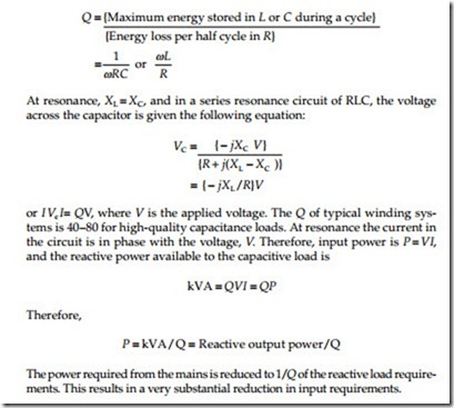
Series resonant testing is used to test very large machines where power frequency (60 Hz) testing cannot be used because of its size and portability. It is been used for field testing of large generators, sulfur hexafluoride (SF6) bus systems, and switchgear. It can also be used for PF, dielectric loss, cable fault location, and corona with some modifications to the test equipment. At series resonance, the energy (I 2R) supplied to the test specimen is dissipated in the insulation system. Energy stored in the tuned circuit (i.e., at resonance) trans- fers back-and-forth between capacitance and inductance each half-cycle. The ratio of energy stored to energy dissipated per half-cycle is known as the qual- ity factor. A higher value of Q gives a low-loss circuit, whereas a low value of Q gives a lossy circuit. Q can be represented by the following equations:
The series resonant method consists of low kVA source input driving a LC series circuit. If breakdown in the capacitive load should occur, the fault cur- rent is limited to a low value by the high inductance value in series with the fault. Furthermore, the output wave form is purely sinusoidal because the harmonics of tuned frequency are attenuated. The attenuation of power frequency harmonics makes series resonance testing very attractive for dielectric loss and PD testing. Consult the manufacturer’s instructions on the operation and use of the series resonance test set.

