Capacitors
Introduction
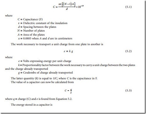
A capacitor consists, basically, of two conductors separated by a dielectric. The operation of a capacitor in a circuit is dependent upon its ability to charge and discharge. When a capacitor charges, an excess of electrons is accumulated on one plate, and a deficiency of electrons is created on the other plate. Capacitance is deter- mined by the size of the conductive material (the plates) and their separation (determined by the type and thickness of the dielectric material). Capacitance is directly proportional to plate size and inversely proportional to the distance between the plates. The unit of capacitance is the farad (F). A capacitance of 1 F results when a potential of 1 V causes an electric charge of 1 coulomb to accumulate on a capacitor.
Basic Principles
The value of a parallel-plate capacitor can be found from
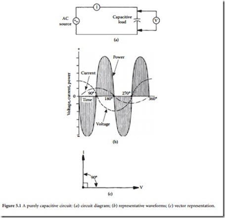
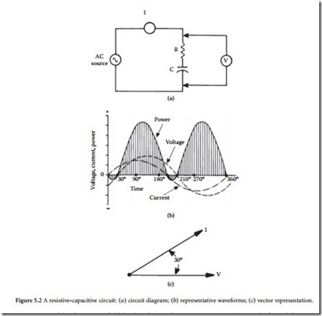
If a direct current is applied to a capacitor, the device will charge to the value of the applied voltage. After the capacitor is fully charged, it will block the flow of direct current. However, if an ac voltage is applied, the changing value of current will cause the device to alternately charge and discharge. In a purely capacitive circuit, the situation shown in Figure 5.1 will exist. The greatest amount of current will flow when the voltage changes most rapidly; that point occurs at the 0 and 180° positions in the sine wave where the polarity reverses. At these positions, maximum current is developed in the circuit, as shown. It is evident by studying the waveform that, in a purely capacitive circuit, voltage will lag current by 90°. Because all practical circuits contain some resistance, a lag of 0 to 90° may be experienced in practice. Fig- ure 5.2 illustrates a case in which voltage lags current by 30º.
Because of the electrostatic field developed around a capacitor, an opposition to the flow of alternat- ing current exists. This opposition is known as capacitive reactance, defined as
The dielectric used for a given capacitor varies, depending upon the application. Common dielectrics include air, gas, mica, glass, and ceramic. Each has a different dielectric constant, temperature range, and thickness.
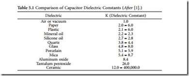
The dielectric constant of a material determines the electrostatic energy that may be stored in that material per unit volume for a given voltage. The value of the dielectric constant expresses the ratio of a capacitor whose dielectric is a vacuum to one using a given dielectric material. The dielectric constant of
air is 1, the reference unit employed for characterizing this parameter. As the dielectric constant is increased or decreased, the capacitance will increase or decrease, respectively. Table 5.1 lists the dielectric constants of various common materials.
The dielectric constant of most materials is affected by both temperature and frequency, except for quartz, Styrofoam, and Teflon, whose dielectric constants remain essentially constant.
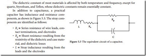
The equivalent series resistance (ESR) of a capacitor is the ac resistance of the device, reflecting both the series resistance (Rs) and the parallel resistance (Rp) at a given frequency. This parameter permits the loss resulting from the foregoing elements to be expressed as a loss in a single resistor in the equivalent circuit.
The power factor (PF) of a capacitor defines the electrical losses in the device operating under an ac voltage. In an ideal device, the current will lead the applied voltage by 90°. A practical capacitor, because of its dielectric, electrode, and contact termination losses, exhibits a phase angle of less than 90°. The power factor of a capacitor is defined as the ratio of the effective series resistance to the impedance of the capacitor. PF usually is expressed as a percentage.
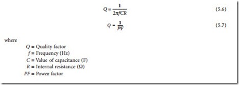
The quality factor (Q) of a capacitor is the ratio of the capacitor reactance to the resistance of the device at a specified frequency. The Q is determined by the equations
Other important specifications for capacitors include:
• Dielectric absorption (DA): The reluctance of the dielectric to give up stored electrons when the capacitor is discharged. This is often called memory because if a capacitor is discharged through a resistance and the resistance is removed, the electrons that remain in the dielectric will reconvene on the electrode, causing a voltage to appear across the capacitor. DA is usually measured by charging the capacitor for 5 min, discharging it for 5 s, then having an open circuit for 1 min, after which the recovery voltage is read. The percentage of DA is defined as the ratio of recovery voltage to charging voltage times 100.
• Dissipation factor (DF): The ratio of the effective series resistance to capacitive reactance. DF normally is expressed as a percentage.
• Leakage current: The current flowing through the capacitor when a dc voltage is applied.
• Insulation resistance: The ratio of the applied voltage to the leakage current. Insulation resistance is normally expressed in megohms.
• Ripple current/voltage: The rms value of the maximum allowable alternating current or voltage (superimposed on any dc level) at a specific frequency at which the capacitor may be operated continuously at a specified temperature.
• Surge voltage: The maximum operating voltage of the capacitor at any temperature.
Series and Parallel Connections
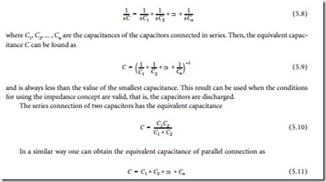
The formulas for series and parallel connection of capacitors can be obtained from the general consider- ation of series and parallel connection of impedances [2]. For series connection
and is always larger than the largest capacitance.
Furthermore, the following two results are useful (for initially discharged capacitors):
• The voltage applied to two capacitors connected in series is divided between these two capacitors inversely proportionally to their capacitance (thus, the larger part of the voltage is on the smaller capacitance).
• The current applied to two capacitors connected in parallel is divided between these two capacitors proportionally to their capacitance (thus, the larger part of the current goes through the larger capacitance).
Practical Capacitors
Practical capacitors can be generally divided capacitors in four broad classes [2]:
• The first class includes low-loss capacitors with good capacitance stability. These are (in accordance with the dielectric) mica, glass, some ceramic, and low-loss plastic film (polypropylene, polysty- rene) capacitors.
• The second class are capacitors of medium loss and medium stability designed to operate over a wide range of dc and ac voltages. These are paper (oil and wax impregnated), plastic film, and some ceramic capacitors. The dc applications include coupling, decoupling, bypass, smoothing and power separating filters, and energy storage. The ac applications include motor start, lightning, interference suppression, and power-line applications (switching and measurement equipment).
• The third class are aluminum and tantalum electrolytic capacitors providing high capacitance in a small size. For the same rated voltage tantalum capacitors have as much as three times larger capacitance per volume unit as aluminum, they are more reliable and have longer service life. The electrolytics are designed for dc and polarized voltage applications. Less-expensive aluminum capacitors are used in radio and television equipment; more expensive tantalum capacitors are destined for military and harsh environmental applications.
• The fourth class are fixed value capacitors (mica, glass, oil, gas, and vacuum) designed for high- voltage (up to 35 kV peak), high-current (up to 200 A) transmitter and power control applications.
The typical construction of common discrete capacitors is illustrated in Figure 5.4. Table 5.2 lists the characteristics of common capacitor types.
