Wiring
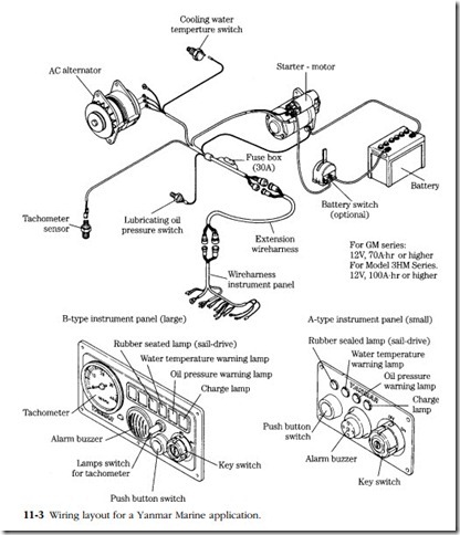
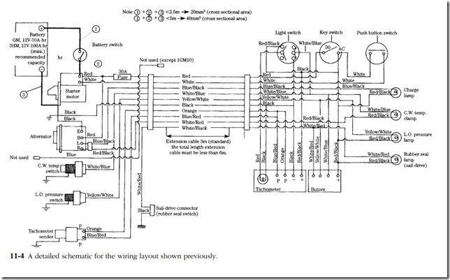
Figure 11-3 illustrates a typical charging/starting system/in quasi-realistic style. The next drawing (Fig. 11-4) is a true schematic of the same system, encoded in a way that conveys the maximum amount of information per square inch.
Neither of these drawings is to scale and the routing of wires has been simplified. The technician needs to know where wires terminate, not what particular routes they take to get there. When routing does become a factor, as in the case of electronic engine control circuitry, the manufacturer should provide the necessary drawings.
Color coding
As is customary, the schematic in Fig. 11-4 indicates the color of the insulation and the size of the various conductors. Color coding has not been completely stan- dardized, but most manufacturers agree that black should represent ground. This does not mean that colors change in a purely arbitrary fashion. In the example schematic, red denotes the positive side of the battery (the ‘hot’ wire); white/blue is associated with the temperature switch; orange with the tachometer, and so on.
Two-color wires consist of a base, or primary, color and a tracer. The base color is always first in the nomenclature. Thus, white/blue means a wire with a blue stripe.
Wiring repairs
The material that follows applies to simple DC starting, charging, and instru- mentation circuits. Cutting or splicing wiring harnesses used with electronic engine management systems can do strange things to the computer.
The first consideration when selecting replacement wire is its current-carrying capacity, or gauge. In the context of diesel engines, two more or less interchangeable
standards apply: the Society of Automotive Engineers (SAE) and Japanese Industrial Standard (JIS).
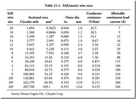
For most wire, the smaller the SAE gauge number, the greater the cross-sectional area of the conductor (See Table 11.1). Thus, #10 wire will carry more current than
#12. The schema reverses when we get into heavy cable: 4/0 is half again as large as 2.0 and has a correspondingly greater current capacity. Note that one must take these current values on faith.
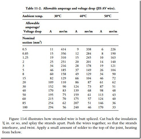
The JIS standard eliminates much confusion by designating wire by type of construction and cross-sectional area. Thus, JIS AV5 translates as automotive-type (stranded) wire with a nominal conductor area of 5 mm2. The Japanese derive current-carrying capacity from conductor temperature, which cannot exceed 60°C (140°F). Ambient temperature and wire type affect the rating, as shown back in Table 4-2.
Vinyl-insulated, stranded copper wire is standard for engine applications. Teflon insulation tolerates higher temperatures than vinyl and has better abrasion resistance. But Teflon costs more and releases toxic gases when burned. In no case should you use Teflon-insulated wire in closed spaces.
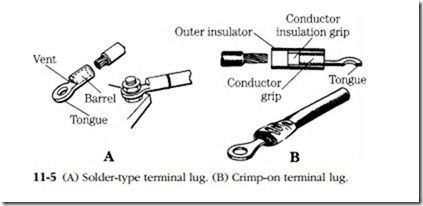
All connections should be made with terminal lugs. Solder-type lugs (Fig. 11-5A) can provide mechanically strong, low-resistance joints and are infinitely preferable to the crimp-on terminals shown in Fig. 11-5B. Insulate with shrink tubing. When shrink tubing is impractical (as when insulating a Y-joint), use a good grade of vinyl electrician’s tape. The 3-M brand costs three times more than the imported variety and is worth every penny.
Soldering
Most mechanics believe they know how to solder, but few have received any training in the art. Applied correctly, solder makes a molecular bond with the base metal. Scrape conductors bright to remove all traces of oxidation.
Use a good grade of low-temperature, rosin-core solder, such as Kessler “blue,” which consists of 60% tin and 40% lead. A 250-W gun should be adequate for all but the heaviest wiring.
The tip of a nonplated soldering iron should be dressed with a file down to virgin copper and tinned, or coated with molten solder. Silver solder is preferable for tinning because it melts at a higher temperature than lead-based solder and so protects the tip from corrosion. Retighten the tip periodically.
The following rules were developed from experience and from a series of experiments conducted by the military:
• Use a minimum amount of solder.
• Wrapping terminal lugs and splicing ends with multiple turns of wire does not add to the mechanical strength of the joint and increases the heat requirement. Wrap only to hold the joint while soldering.
• Heat the connection, not the solder. When the parts to be joined are hot enough, solder will flow into the joint.
• Do not move the parts until the solder has hardened. Movement while the solder is still plastic will produce a highly resistive “cold” joint.
• Use only enough heat to melt the solder. Excessive heat can damage nearby components and can crystallize the solder.
• Allow the joint to air cool. Dousing a joint with water to cool it weakens the bond.
