Solenoids
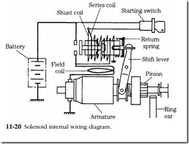
Almost all diesel starters are engaged by means of a solenoid mounted on the frame. At the same time the solenoid plunger moves the pinion, it closes a pair of contacts to complete the circuit to the starter motor. In other words the component
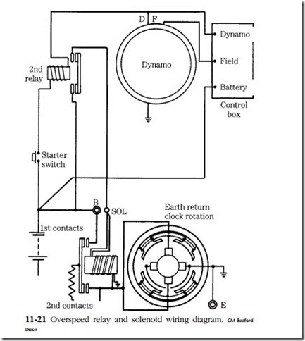
consists of a solenoid or linear motor and a relay (Fig. 11-20). Some circuits feature a second remotely mounted relay, as shown in Figs. 11-20 and 11-21. The circuit depicted in the earlier illustration was designed for marine use.
The starter switch might be 30 ft or more from the engine. To cut wiring losses a second relay is installed, which energizes the piggyback solenoid. The additional relay (2nd relay in Fig. 11-21) also gives overspeed protection should the switch remain closed after the engine fires. It functions in conjunction with a direct current generator. Voltage on the relay windings is the difference between generator output and battery terminal voltage. When the engine is cranking, generator output is functionally zero. The relay closes and completes the circuit to the solenoid. When the engine comes up to speed, generator output bucks battery voltage and the relay opens, automatically disengaging the starter. As admirable as such a device is, it should not be used continually, because some starter overspeeding will still occur, with detrimental effects to the bearings.
Should the generator circuit open, the starter will be inoperative because the return path for the overspeed relay is through the generator. In an emergency the engine can be started by bridging the overspeed terminals. Of course, the transmission or other loads must be disengaged and, in a vehicle, the handbrake must be engaged.
In addition, you will notice that the solenoid depicted in Fig. 11-21 has two sets of contacts. One set closes first and allows a trickle of current to flow through the resistor (represented by the wavy line above the contact arm) to the motor. The arma- ture barely turns during the engagement phase. But once engaged a trigger is released and the second set of contacts closes, shunting the resistor and applying full battery current to the motor. This circuit, developed by CAV, represents a real improvement over the brutal spin-and-hit action of solenoid-operated and inertia clutches and should result in longer life for all components, including the flywheel ring gear.
Solenoids and relays can best be tested by bridging the large contacts. If the starter works, you know that the component has failed. Relays are sealed units and are not repairable. But most solenoids are at least amenable to inspection. Repairs to the series or shunt windings (illustrated in Figs. 11-20 and 11-21) are out of the question unless the circuit has opened at the leads. Contacts can be burnished, and some designs have provision for reversing the copper switch element.


