Conductor Insulation Tests
The insulation failure between conductors of motors and generators depends upon the machine insulation design. Failure between conductors can be as likely as the failure of ground insulation. Coils are tested during manufacture well above the minimum sparking voltage to ensure that the coils do not fail owing to thermal effects, vibrations, and the like. Where a high level of reliability is needed, maintenance testing of conductor insulation should be performed to the level of new coil test values. Normally, this test should be performed at the factory or repair shop facilities. The following test methods are in common use:
• Surge comparison test (see Section 10.9.11)
• Induced surge voltage test
• Rotating spark-gap-type high-frequency oscillator
Motor and Generator Component Tests
These tests include insulation resistance tests on components of motors and generators such as RTDs, exciter windings, stator insulated through bolts, rotor windings, and so on. These tests consist of the following:
1. Resistance measurement and insulation resistance of the RTDs
2. Insulation resistance of insulated stator-through-bolts
3. Test the interlaminar insulation of stator core
4. Rotor winding tests
a. Insulation resistance
b. Winding resistance
c. Winding impedance
d. Winding flux distribution (pole voltage drop test)
The reader should consult the equipment manufacturer for recommendations or the pertinent IEEE standard such as IEEE-56-1991, IEEE-95-2007, and IEEE-112-2004 on conducting these tests.
Voltage Surge Comparison Test
It is a well-known fact that many motor failures begin as turn-to-turn shorts within a single winding. These turn-to-turn shorts then create hot spots which in turn degrade the insulation in adjacent turns until the entire winding fails. The mechanism of this type of failure may take a long time to develop depend- ing upon the operating characteristics of the motor. This type of failure or degradation cannot be detected by the insulation resistance test (megohmmeter) or high-potential testing because of its incipient nature; however, this type of incipient type of fault can be detected by surge comparison testing. Many types of faults may be detected by the use of surge testing, such as turn-to turn, coil-to-coil, phase-to-phase as well as opens and grounds.
The surge comparison tester is used to simultaneously test turn-to-turn, coil-to-coil, and coil-to-ground insulation. The surge tester is an electronic device that applies surge voltage stress between turns of a coil, between phases, from winding to ground, and it can detect short-circuited turns in windings under test. The surge voltage is of very short duration and there- fore will not damage the windings. However, the surge voltage can be increased high enough so that insulation breakdown and arcing can be observed. The surge comparison test can be used as a go or no-go test. This test is a very useful diagnostic test for quality-control shop testing when reconditioning or rewinding wound components and in the field to detect early impending winding insulation failures. Rewound and reconditioned motors and generators should be given a surge comparison test before varnishing so that winding faults, such as shorted turns or coils, reversed coil groups or phases, and incorrect number of turns in a coil, can be corrected before the windings are treated with varnish.
Surge testing is accomplished by impressing pulses of very rapid rise from a surge comparison tester (capacitor) into the machine windings. These pulses each produce a damped oscillation of current, or resonant frequency, between the capacitor of the tester and the winding. The pulse and the result- ing oscillation is monitored by means of an oscilloscope. Then by observing the pattern on the oscilloscope, the existence and nature of the fault in the machine winding can be determined.
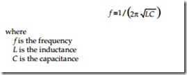
Surge Comparison testing is an extension of the principle of simple surge testing. If for example, we knew what inductance a winding should have, we could look at the single wave pattern and be assured that it is the correct frequency. That frequency of oscillation would be
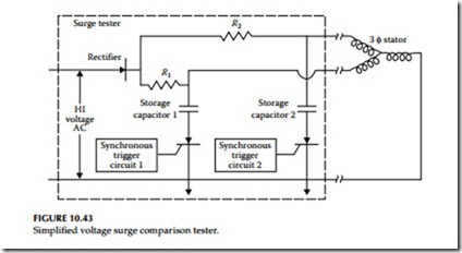
Since we seldom know the inductance value of a machine winding accurately, we need a more flexible yet accurate method to analyze a signal trace on the oscilloscope. To do this, we use a dual trace scope and two identical capacitance discharge circuits to charge two different machine windings that should match at the same time. For example, in the testing of three-phase machine stator we know that each of the three phases should have the same inductance. Consequently, by comparing one phase against another we have two complete, and hopefully, identical L-C circuits for our test to work. A simplified schematic of the surge comparison tester is shown in Figure 10.43. Detection of one-turn shorts or grounded coil is possible in all windings of few parallel circuits. Often only a small trace separation may be detectable with a one-turn short in a very large motor that has several parallel paths per phase. However, the winding connections can be broken to reduce the parallel paths in order to obtain a larger trace.
It may be difficult to indicate the type of fault from the wave shape observed on the oscilloscope; however, a double trace indicates that a definite fault exists, which should be investigated. Double lines at the top of the trace and at the horizontal centerline for formed and mush-wound stators are typical and do not indicate faults.
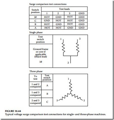
The surge comparison tester is a universal type instrument capable of test- ing single- and three-phase machine windings. Single-phase windings should be tested in pairs whereas the three-phase windings should be tested two phase windings at a time. Single-phase and three-phase machine windings of various sizes can be tested as shown in the connection diagram of Figure 10.44. The waveshapes for typical winding faults for the wye- and delta-connected machines are shown in Figure 10.45.


