Installation notes
Measurement systems are generally based on low voltages and are consequently vulnerable to electrical noise. In most plants, a PLC may be controlling 415 V motors at 100 A, and reading thermocouple signals of a few millivolts. Great care must be taken to avoid interference from the higher power signals.
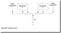
The first precaution is to take care with the earthing layout. A badly laid out system as shown in Fig. 4.49 provides common return paths, and currents from the load returning through the common impedances Z1 to Z3 will induce error voltages into the low level analogue circuit. There are at least three distinct types of earth in a system, these being a safety earth (as used for doors, frames etc.), a dirty earth (used for higher voltage and higher current signals), and a clean earth, for low voltage analogue signals. These should meet at only one point.
Screened cable should be used for all analogue signals, foil screening being pre- ferred to braided screen. The screen should be earthed at one point only (ideally the receiving end) as any difference in earth between the two earthing points will cause current to flow in the screen (as in Fig. 4.50) and induce noise into the signal lines. When a screened cable passes through intermediate junction boxes, screen continuity must be maintained, and the screen must be sleeved to prevent it from touching the frame of the junction boxes.
High voltage and low voltage cable should be well separated; most manufacturers suggest at least one metre between 415 V and low voltage cables, but this can be dif- ficult to achieve in practice. It is a good practice to use trunking or conduit for low voltage signals as a way of identifying them for future installers. The same result can also be achieved using cables with differently coloured PVC sleeves. Inevitably high voltage and low voltage cables will have to cross at some points. If adequate spacing cannot be achieved, these crossings should always be at 90°.
Further commentary on interference is given in section 14.2.

