Transmission-System Grounding
Nature can devastate a communications site. Lightning can seriously damage an unprotected facility with little or no warning, leaving an expensive and time-consuming repair job. The first line of defense is proper grounding of the communications system.
Transmission Line
All coax and waveguide lines must include grounding kits for bonding the transmission line at the antenna [1]. On conductive structures, this can be accomplished by bonding the tail of the grounding kit to the structure itself. Remove all nonconductive paint and corrosion before attachment. Do not drill holes, and do not loosen any existing tower member bolts. Antenna clamping hardware can be used, or an all-stainless-steel hose clamp of the appropriate size can be substituted. The location of the tower-top ground is not as critical as the bottom grounding kit.
On nonconductive structures, a no. 1/0 or larger wire must be run down the tower [1]. Bond the transmission-line grounding kit to this down-run. Keep the wire as far away from all other conductive runs (aviation lights, coax, and waveguide) as possible. Separation of 2 ft is preferred; 18 in. is the mini- mum. If any other ground lines, conduit, or grounded metallic-structure members must be traversed that are closer than 18 in., they too must be grounded to the down-lead ground line to prevent flashover.
At the point where the coax or waveguide separates from the conductive structure (metal tower), a coax or waveguide grounding kit must be installed. Secure the connection to a large vertical structure member with a small number of joints. Attach to a structural member as low as possible on the tower.
Dress the grounding kit tails in a nearly straight 45° downward angle to the tower member. On non- conductive structures, a metal busbar must be used. Ground the bar to one or more of the vertical down- conductors and as close to ground level as possible.
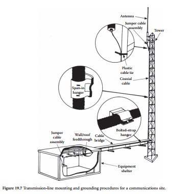
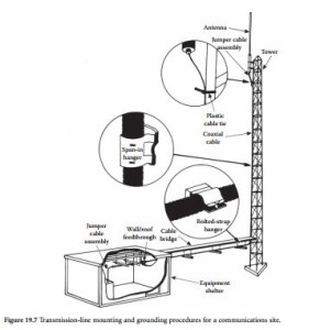
Coaxial cables, lighting conduit, and other lines on the tower must be secured properly to the structure. Figure 19.7 illustrates several common attachment methods.
Cable Considerations
Ground-strap connections must withstand weathering and maintain low electrical resistance between the grounded component and earth [1]. Corrosion impairs ground-strap performance. Braided-wire ground straps should not be used in outside installations. Through capillary action resembling that of a wick, the braid conveys water, which accelerates corrosion. Eventually, advancing corrosion erodes
the ground-strap cable. Braid also can act as a duct that concentrates water at the bond point. This water speeds corrosion, which increases the electrical resistance of the bond. A jacketed, seven-strand copper wire strap (no. 6 to no. 2) is recommended for transmission-line grounding at the tower.
Satellite Antenna Grounding
Most satellite receiving/transmitting antenna piers are encapsulated in concrete [1]. Consideration should be given, therefore, to implementing a Ufer ground for the satellite dish. A 4-in-diameter pipe, submerged 4 to 5 ft in an 18-in.-diameter (augered) hole, will provide a good start for a Ufer-based ground system. It should be noted that an augered hole is preferred because digging and repacking the soil around the pier will create higher ground resistance. In areas of good soil conductivity (100 Ω/m or less), this basic Ufer system may be adequate for the antenna ground.
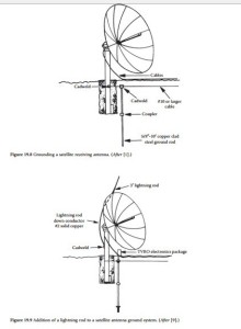
Figure 19.8 shows the preferred method: a hybrid Ufer/ground-rod and radial system. A cable con- nects the mounting pipe (Ufer ground) to a separate driven ground rod. The cable then is connected to the facility ground system. In areas of poor soil conductivity, additional ground rods are driven at incre- ments (2.2 times the rod length) between the satellite dish and the facility ground system. Run all cables underground for best performance. Make the interconnecting copper wire no. 10 size or larger; bury the wire at least 8 in. below finished grade. Figure 19.9 shows the addition of a lightning rod to the satellite dish.


