Facility Ground Interconnection
Any radial that comes within 2 ft of a conductive structure must be tied into the ground system [1]. Bury the interconnecting wire, if possible, and approach the radial at a 45° angle, pointing toward the expected surge origin (usually the tower). Cadweld the conductor to the radial and to the structure.
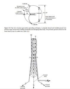
For large-base, self-supporting towers, the radials should be split among each leg pad, as shown in Figure 19.4. The radials may be brought up out of the soil (in air) and each attached at spaced locations around the foot pad. Some radials may have to be tied together first and then joined to the foot pad. Remember, if space between the radial lines can be maintained, less mutual inductance (coupling) will exist, and the system surge impedance will be lower.
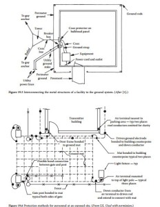
It is desirable to have a continuous one-piece ring with rods around the equipment building. Connect this ring to one, and only one, of the tower radials, thus forming no radial loops. (See Figure 19.5.) Bury the ring to the same depth as the radials to which it interconnects. Connect power-line neutral to the ring. Warning: Substantial current may flow when the power-line neutral is connected to the ring. Follow safety procedures when making this connection.
Install a ground rod (if the utility company has not installed one) immediately outside the generator or utility company vault, and connect this rod to the equipment building perimeter ground ring. Route a no. 1/0 insulated copper cable from the main power panel inside the generator vault to the ground rod outside the vault. Cut the cable to length, strip both ends, and tie one end to the power-line neutral at the main power panel in the generator vault. Connect the other end to the ground rod. Warning: Use care when making this connection. Hazardous voltage may exist between the power-line neutral and any point at earth potential.
Do not remove any existing earth ground connections to power-line neutral, particularly if they are installed by the power company. To do so may violate the local electrical code. The goal of this interconnection is to minimize noise that may be present on the neutral and to conduct this noise as directly as possible outside to earth ground.
Personnel Protection
The threat to personnel during a lightning strike ranges from the obvious danger of direct contact with a light- ning strike to the more obscure effects of step and touch voltages [2]. Protection from a direct strike when near or within structures is accomplished with traditional rolling sphere concept methods. Step and touch potentials, however, are created as a lightning current passes through resistive soil and other available paths as it dis- sipates into the earth. A person in contact with only one point of the gradient will simply rise and fall in potential with the gradient without injury. A person in contact with multiple points on the earth or objects at different potentials along the gradient, however, will become part of the current path and may sustain injury or death.
Figure 19.6 [3, 4] indicates a number of methods for protecting personnel from the direct and secondary effects of lightning. A typical tower/transmitter site is used as an example. A technician responding to a service problem during a thunderstorm would likely exit his or her vehicle outside the gate, unlock and open the gate, and move the vehicle into the inside yard. The technician would then leave the vehicle and enter the building.
The threat of a direct lightning strike to the technician has been minimized by establishing a protective zone over the areas to be traversed. This zone is created by the tower and air terminals mounted atop light poles.
Step potentials are minimized through the use of a ground mat buried just below the surface of the area where the technician is expected to be outside the vehicle. Ground mats are commercially available, fabricated in a 6-in. × 6-in. square pattern using no. 8 AWG bare copper wire. Each intersection is welded, creating — for all practical purposes — an equipotential area that minimizes the step potential gradient in the area above the mat. The mat, as a whole, will rise and fall in potential as a result of the lightning
current discharges; however, there will be very little difference in potential between the technician’s feet. Mats should be covered with 6 in. of crushed stone or pavement.
The threat of dangerous touch potentials is minimized by bonding the following elements to the ground system:
• Personnel ground mat
• Fence at each side of the gate opening
• Door frame of the transmitter building
• Flexible bonding connection between the swing gate and its terminal post Such bonding will ensure that the object being touched by the technician is at or near the same potential as his or her feet.
Bonding both sides of the gate opening to the mat helps to ensure that the technician and both sides of the gate are at approximately the same potential while the gate is being handled. The flexible bond between the gate and its support post can be accomplished using a commercially available kit or by Cad- welding a short length of flexible no. 2/0 AWG welding cable between the two elements.


