AC Circuit Analysis
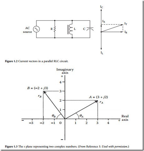
Vectors are used commonly in ac circuit analysis to represent voltage or current values. Rather than using waveforms to show phase relationships, it is accepted practice to use vector representations (sometimes called phasor diagrams). To begin a vector diagram, a horizontal line is drawn, its left end being the reference point. Rotation in a counterclockwise direction from the reference point is considered to be positive. Vectors may be used to compare voltage drops across the components of a circuit containing resistance, inductance, or capacitance. Figure 1.1 shows the vector relationship in a series RLC circuit, and Figure 1.2 shows a parallel RLC circuit.
Power Relationship in AC Circuits
In a dc circuit, power is equal to the product of voltage and current. This formula also is true for purely resistive ac circuits. However, when a reactance — either inductive or capacitive — is present in an ac cir- cuit, the dc power formula does not apply. The product of voltage and current is, instead, expressed in volt-amperes (VA) or kilovoltamperes (kVA). This product is known as the apparent power. When meters are used to measure power in an ac circuit, the apparent power is the voltage reading multiplied by the current reading. The actual power that is converted to another form of energy by the circuit is measured with a wattmeter, and is referred to as the true power. In ac power-system design and operation, it is desir- able to know the ratio of true power converted in a given circuit to the apparent power of the circuit. This ratio is referred to as the power factor.
Complex Numbers
A complex number is represented by a real part and an imaginary part. For example, in A = a + jb , A is the complex number; a is real part, sometimes written as Re(A) and b is the imaginary part of A, often
written as Im(A). It is a convention to precede the imaginary component by the letter j (or i). This form of writing the real and imaginary components is called the Cartesian form and symbolizes the complex (or s) plane, wherein both the real and imaginary components can be indicated graphically [3]. To illustrate this, consider the same complex number A when represented graphically, as shown in Figure 1.3. A second complex number B is also shown to illustrate the fact that the real and imaginary components can take on both positive and negative values. Figure 1.3 also shows an alternate form of representing complex numbers. When a complex number is represented by its magnitude and angle, for example,
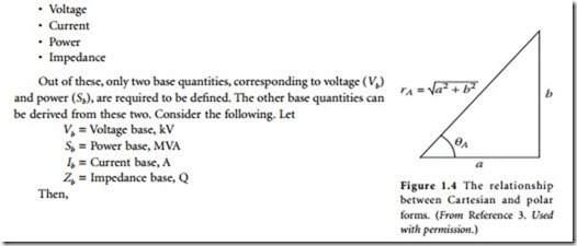
To see the relationship between the Cartesian and the polar forms, the following equations can be
Conceptually, a better perspective can be obtained by investigating the triangle shown in Figure 1.4, and considering the trigonometric relationships. From this figure, it can be seen that
Phasors
The ac voltages and currents appearing in distribution systems can be represented by phasors, a concept useful in obtaining analytical solutions to one-phase and three-phase system design. A phasor is generally defined as a transform of sinusoidal functions from the time domain into the complex-number domain and given by the expression
where V is the phasor, V is the magnitude of the phasor, and θ is the angle of the phasor. The convention used here is to use boldface symbols to symbolize phasor quantities. Graphically, in the time domain, the phasor V would be a simple sinusoidal wave shape, as shown in Figure 1.5. The concept of a phasor leading or lagging another phasor becomes very apparent from the figure.
Phasor diagrams are also an effective medium for understanding the relationships between phasors. Figure 1.6 shows a phasor diagram for the phasors represented in Figure 1.5. In this diagram, the convention of positive angles being read counterclockwise is used. The other alternative is certainly possible, as well. It is quite apparent that a purely capacitive load could result in the phasors shown in Figure 1.5 and Figure 1.6.
Per Unit System
In the per unit system, basic quantities such as voltage and current are represented as certain percentages of base quantities. When so expressed, these per unit quantities do not need units, thereby making numerical analysis in power systems somewhat easier to handle. Four quantities encompass all variables required to solve a power system problem. These quantities are:


