Clamp-On Ground Resistance Measurement
This measurement method is new and quite unique. It offers the ability to measure the resistance without disconnecting the ground. This type of measurement also offers the advantage of including the bonding to ground and the overall grounding connection resistances.
Principle of Operation
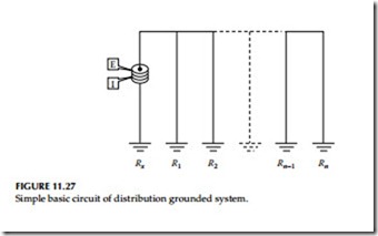
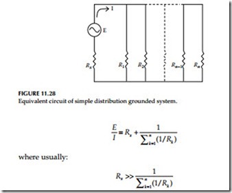
Usually, a common distribution line grounded system can be simulated as a simple basic circuit as shown in Figure 11.27, or an equivalent circuit as shown in Figure 11.28. If voltage E is applied to any measured grounding pole Rx through a special transformer, current I flows through the circuit, thereby establishing the following equation:
Refer again to Figures 11.27 and 11.28. Current is fed to a special transformer via a power amplifier from a 1.6 kHz constant-voltage oscillator. This current is detected by a detection current transformer (CT). Only the 1.6 kHz signal frequency is amplified by a filter amplifier before being fed into analog/ digital (A/D)-converter, and after synchronous rectification it is displayed on the liquid crystal display (LCD).
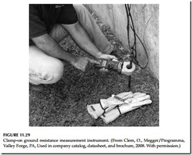
The filter amplifier is used to cut off earth current at commercial frequency and high-frequency noise. Voltage is detected by coils wound around the injection CT and then amplified and rectified to be compared by a level comparator. If the clamp is not closed properly, an open jaws annunciator appears on the LCD. The clamp-on ground resistance measurement instrument is shown in Figure 11.29.
In-Field Measurement
The following are examples of ground resistance measurements in typical field situations:
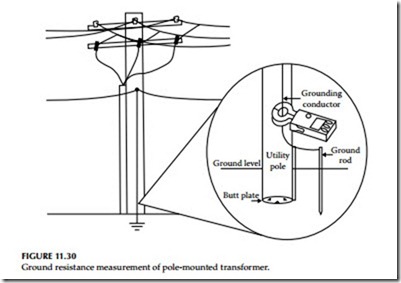
Pole-mounted transformer: Remove any molding covering the ground conductor, and provide sufficient room for the jaws of the clamp-on ground tester. The jaws must be able to close easily around the conductor. The jaws can be placed around the ground rod itself.
Note: The clamp must be placed so that the jaws are in electrical path from the system neutral or ground wire to the ground rod or rods as the circuit provides.
Select the current range A. Clamp onto the ground conductor and measure the ground current. The maximum range is 30 A. If the ground current exceeds 30 A, ground resistance measurements are not possible. “Do not proceed further with the measurement.” Having noted the ground current, select the ground resistance range Ω and measure the resistance directly.
The reading you measure with the ground tester indicates not just the resistance of the rod, but of the connection to the system neutral and all bonding connections between the neutral and the rod.
Note that in Figure 11.30, there exist both a butt plate and a ground rod.
In this type of circuit, it is necessary to place the tester jaws above the bond so that both grounds are included in the test. For future reference, note the date, ohms reading, current reading, and pole number. Replace any molding you may have removed from the conductor.
Note: A high reading indicates one or more of the following: Poor ground rod.
Open ground conductor.
High resistance bonds on the rod or splices on the conductor; watch for buried split butts, clamps, and hammer-on connections.
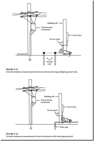
Service entrance or meter: Follow basically the same procedure as in the first example. Notice that Figure 11.31 shows the possibility of multiple ground rods and in Figure 11.32, the ground rods have been replaced with a water pipe ground. You may also have both types acting as a ground. In these cases, it is necessary to make the measurements between the service neutral and both grounded points.
Pad-mounted transformer
Note: Never open transformer enclosures. They are the property of the electrical utility. If the ground test needs to be performed with the utility transformer, coordinate with the utility personnel for such a test.
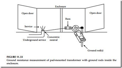
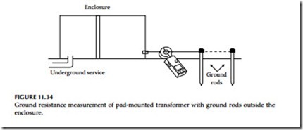
“Observe all safety requirements—dangerously high voltage is present.” Locate and number all rods (usually only a single rod is present). If the ground rods are inside the enclosure, refer to Figure 11.33 and if they are outside the enclosure, refer to Figure 11.34. If a single rod is found within the enclosure, the measurement should be taken on the conductor just before the bond on the ground rod. Often, more than one ground conductor is tied to this clamp, looping back to the enclosure or neutral.
In many cases, the best reading can be obtained by clamping the instrument onto the ground rod itself, below the point when the ground conductors are attached to the rod, so that you are measuring the ground circuit. Care must be taken to find a conductor with only one return path to the neutral.
Generally, a very low reading at the measurement indicates that you are on a loop and you need to test closer to the rod. In Figure 11.34, the ground rod
is located outside the enclosure. Clamp at the indicated measuring point to obtain the correct reading. If more than one rod exists at different comers of the enclosure, it will be necessary to determine how they are connected to properly measure the ground resistance.
Transmission Towers
“Observe all safety requirements—dangerously high voltage is present.” Locate the ground conductor at the base of the tower.
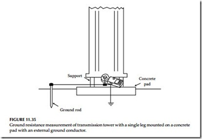
Note: Many different configurations exist. Care should be taken when searching for the ground conductor. Figure 11.35 shows a single leg mounted on a concrete pad with an external ground conductor. The point at which you clamp the ground tester should be above all splices and connections which allow for multiple rods, butt wraps, or butt plates.
Central Office Locations
The main ground conductor from ground window or ground plane is often too large to clamp around. Due to the wiring practices within the central office, there are many locations at which you can look at the water pipe or counterpoise from within the building. An effective location is usually at the ground buss in the power room, or near the backup generator.
By measuring at several points and comparing the readings, you will be able to identify neutral loops, utility grounds, and central office grounds. The test is effective and accurate because the ground window is connected to the utility ground at only one point, according to standard practices.
