Soil Resistivity Measurements (Four-Point Measurement)
The purpose of soil resistivity measurements is threefold. First, such data are used to make subsurface geophysical surveys as an aid in identifying ore locations, depth to bedrock, and other geological phenomena. Second, resistivity has a direct impact on the degree of corrosion in underground pipe- lines. A decrease in resistivity relates to an increase in corrosion activity and therefore dictates the protective treatment to be used. Third, soil resistivity directly affects the design of a grounding system, and it is to that task that this discussion is directed. When designing an extensive grounding system, it is advisable to locate the area of lowest soil resistivity in order to achieve the most economical grounding installation.
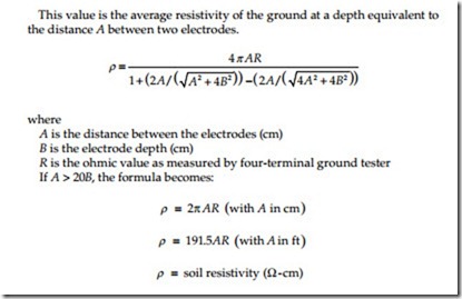
The two types of resistivity measurements are two-point method and four- point method. The two-point method is simply the resistance measured between two points. For most applications, the most accurate method is the four-point method. The four-point method, as the name implies, requires the insertion of four equally spaced, and in-line, electrodes into the test area. A known current from a constant current generator is passed between the outermost electrodes. The potential drop (as a function of the resistance) is then measured across the two innermost electrodes. The ground resistivity is based on the formula given below and the meter is calibrated to read directly in ohms.
This value is the average resistivity of the ground at a depth equivalent to the distance A between two electrodes.
Touch Potential Measurements
The primary reason for performing ground resistance measurements is to ensure electrical safety of personnel and equipment. Periodic ground electrode or grid resistance measurements are recommended when:
1. The electrode/grid is relatively small and can be conveniently disconnected
2. Corrosion induced by low soil resistivity or galvanic action is suspected
3. Ground faults are very unlikely to occur near the ground under test
In certain cases, the degree of electrical safety can be evaluated from a different perspective. Voltage gradient are a safety concern in large high- voltage switchyards and substations. Therefore, the ground grid system of these facilities is designed to ensure that the voltage gradients due to induced or fault currents remain at low value and not pose a danger to personnel or equipment. The maximum limit of voltage for these gradients is defined in terms of the following:
Touch potential: Touch potential is the voltage difference between a person’s arm and the feet, caused by the voltage gradient due to fault or induced current. It is assumed that the current passes through the heart and therefore this potential should be kept to near zero to safeguard personnel who might accidentally come in contact with equipment and structures in a switchyard or substations.
Step potential: Step potential is the voltage difference between a person’s feet, caused by the voltage gradient due to fault or induced current. It is assumed that the current passes through the legs and therefore this potential should be kept to near zero to safeguard personnel.
Touch potential measurements are recommended when the following factors are present.
1. It is physically or economically impossible to disconnect the ground to be tested.
2. Ground faults could reasonably be expected to occur near the ground to be tested, or near equipment grounded by the ground to be tested.
3. The footprint of grounded equipment is comparable to the size of the ground to be tested. (The footprint is the outline of the part of equipment in contact with the earth.)
When performing touch potential measurements, a four-pole ground resistance tester is used. During the test, the instrument induces a low-level fault into the earth at some proximity to the subject ground. The instrument displays touch potential in volts per ampere of fault current. The displayed value is then multiplied by the largest anticipated ground fault current to obtain the worst case touch potential for a given installation.
For example, if the instrument displayed a value of 0.100 when connected to a system where the maximum fault current was expected to be 5000 A, the maximum touch potential would be 500 V.
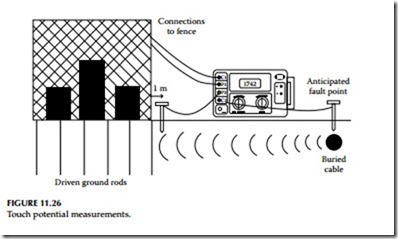
Touch potential measurements are similar to fall-of-potential measurements in that both measurements require placement of auxiliary electrodes into or on theearth.Spacingtheauxiliaryelectrodesduringtouchpotentialmeasurements differs from fall-of-potential electrode spacing, as shown in Figure 11.26.
Consider the following scenario: If the buried cable depicted in Figure 11.26 experienced an insulation breakdown near the substation shown, fault currents would travel through the earth toward the substation ground, creating a voltage gradient. This voltage gradient may be hazardous or potentially lethal to personnel who came in contact with the affected ground.
To test for approximate touch potential values in this situation, proceed as follows. Connect cables between the fence of the substation and C1 and P1 of the four-pole earth resistance tester. Position an electrode in the earth at the point at which the ground fault is anticipated to occur, and connect it to C2. In a straight line between the substation fence and the anticipated fault point, position an auxiliary electrode into the earth 1 m (or one arm’s length) away from the substation fence, and connect it to P2. Turn the instrument on, select the 10 mA current range, and observe the measurement. Multiply the dis- played reading by the maximum fault current of the anticipated fault. By positioning the P2 electrode at various positions around the fence adjacent to the anticipated fault line, a voltage gradient map may be obtained.

