Circuit Breaker Contact Resistance Measurement Test
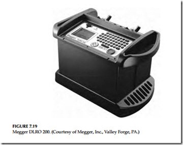
Stationary and moving contacts are built from alloys that are formulated to endure the stresses of electrical arcing. However, if contacts are not maintained on a regular basis, their electrical resistance due to repeated arcing builds up, resulting in a significant decrease in the contact’s ability to carry current. Excessive corrosion of contacts is detrimental to the breaker performance. One way to check contacts is to apply DC and measure the contact resistance or voltage drop across the closed contacts. The breaker contact resistance should be measured from bushing terminal to bushing terminal with the breaker in closed position. It is recommended that for MV and HV the resistance test be made with 100 A or higher DC. The use of a higher current value gives more reliable results than using lower current values. The resistance value is usually measured in microohms (μΩ). The average resistance value for 15 kV class circuit breakers is approximately between 200 and 250 μΩ. Several companies make good, reliable microohmmeters to perform this testing. One such instrument is the Megger DLRO 200. It can generate test currents from 10 to 200 A and can measure resistances ranging from 0.1 μΩ to 1 Ω. The Megger DLRO 200 is shown in Figure 7.19.
Circuit Breaker Time–Travel Analysis
This test is usually performed on MV and HV circuit breakers, usually 34 kV and above, to detect problems in the breaker operating mechanism. This test can be conducted with a mechanical or electronic time–travel analyzer. Today, the electronic time–travel analyzers are replacing the old mechanical
time–travel analyzers. With either analyzer information on the breaker oper- ating mechanism is provided in form of charts or graphs which can be used to assess the mechanical and electrical condition of the breaker. There are nine tests that are usually conducted on the breaker with the circuit breaker analyzer. These tests are (1) closing time and opening time, (2) contact bounce,
(3) opening and closing synchronization, (4) closing and opening speed (velocity and displacement), (5) trip operation, (7) trip-free operation, (8) close operation, and (9) trip-close operation.
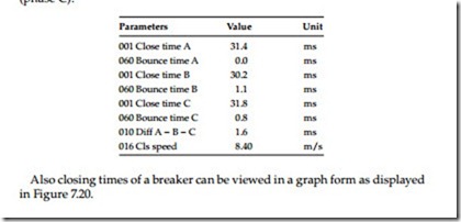
Closing and opening time: In the example below, the closing time of the contacts is shown to be 31.4 ms (phase A), 30.2 ms (phase B), and 31.8 ms (phase C).
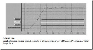
Also closing times of a breaker can be viewed in a graph form as displayed in Figure 7.20.
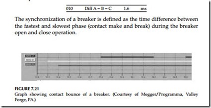
Contact bounce: If we expand the x-axis in Figure 7.20, we can actually view the contact bounce associated with the above breaker operation as shown in Figure 7.21.
It is clear to see that there is 0.8 ms bounce associated with the contact movement in phase C. These series of contact bounces can be compared with future tests to see if there is any degradation to the actual mechanism associ- ated with breaker contacts.
Opening and closing synchronization: The breaker opening and synchroniza- tion can be viewed as a group, i.e., the operation of all three phases together for breaker open and close cycle. This information will indicate whether the breaker contacts open and close together or how far apart the three-phase contacts are relative to each other during the close and open cycle as shown in the example below. The normal maximum time difference between all three phases should not be more than 2 ms for most breakers.
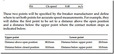
Total opening and closing speed: All breakers have specific speed, opening and closing times; therefore, it is important that breakers operate within their opening and closing time. For example, if a breaker is slow to open due to ageing or degradation, it may compromise the protection and coordination scheme of the protective relays, and thereby cause unwanted power inter- ruption and equipment damage. Further, all breakers have specified closing speed which is defined as the average speed calculated between two defined points on the motion curve as indicated below.
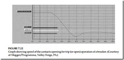
Trip operation: The trip operation of a breaker is another name for an open operation. Most utility companies and plant owners want to perform a trip (or open) operation to monitor the speed of the opening mechanism and contacts to make sure there is enough energy in the spring mechanism to open under a fault condition. The graph for a trip is similar to the one for a close operation, except the motion of the mechanism is going in the oppo- site direction, i.e., from closed contacts to fully open position as seen in Figure 7.22.
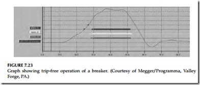
Trip–free operation: This operation simulates the condition when an open breaker is closed into a fault and then it is tripped free by a protective relay. Trip-free is an operation where the breaker contacts are in the open position and the breaker is operated to perform a close–open sequence. In this oper- ation, the breaker is closed and then immediately sent a control command to open. This operation confirms whether a breaker, if closed into a fault, can clear it. The graph for a trip-free operation is shown in Figure 7.23.
Close operation: This test is performed to verify a breaker’s closing mecha- nism. The graph for close operation of a breaker is shown in Figure 7.24 which is similar to the graph of Figure 7.20.
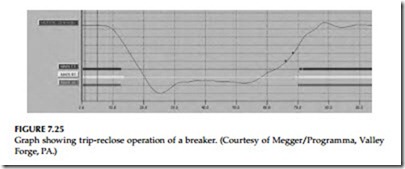
Trip-reclose operation: In this test, the reclose operation of the breaker is checked to assure that the breaker closing time is within specified limits after a trip operation. The reclose time is measured either in milliseconds or cycles. The trip-reclose operation of the breaker is shown in Figure 7.25.
The problems usually detected with this test are faulty dashpots, faulty adjustments, weak accelerating springs, defective shock absorbers, buffers and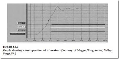
closing mechanisms, or broken parts. This test should be performed during acceptance tests and then during maintenance tests about every 3 years.
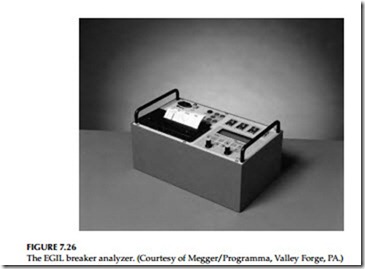
The breaker opening and closing parameters can easily be measured with a Megger Programma EGIL breaker analyzer or its equivalent manufactured by other vendors. The EGIL is designed to test MV breakers that have a common operating mechanism and a single break per phase. All three phases can be tested at the same time giving both individual phase timing and com- bined measurements for all three phases. The EGIL analyzer is shown in Figure 7.26.
Related posts:
Incoming search terms:
- @sales mail
- sites: @sales mail
- resistance of circuit breker
- Electrical Switchgear mail
- Electrical Switchgear Industries Contact us mail
- distributors and manufacturers of Switchgear and Switchboard Apparatus @sales 2019 emails contacts us mail
- contact resistance test of medium voltage circuit breaker
- contact resistance of a circuit breaker
- contact resistance measurement switchgear
- contact resistance measurement circuit diagram Switchgear
- Circuit Breaker manufacturers mail
- switchgear contact resistance values
