Ground Grid Integrity Measurements
Neither the ground resistance measurements or the touch potential measurements provide information on the ability of grounding conductors and connections to carry ground fault currents safely to earth. Experience has shown that the ground fault current can cause a lot of damage to equipment and pose safety hazard to personnel when it does not find a low-impedance path to the ground grid and thus to mother earth. Therefore, it makes sense to periodically check and verify the integrity of the ground grid connections.
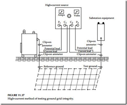
The objective of this measurement is to determine whether the equipment, frame, structures, or enclosure grounds are connected to the grounding electrode or ground grid with low resistance. The resistance value of such connections is expected to be very low (100 μΩ or less). The best way for making tests for integrity of ground grid connections is to use a large but practical current and some means of detecting the voltage drop caused by this current. A test set is available to conduct this measurement using AC current. This test method is known as the high-current test method. This method consists of passing 300 A through the ground grid between a reference ground (usually a transformer neutral) and the ground (conductor and connections) to be tested. The voltage drop and the current magnitude and direction are monitored to verify the integrity of the ground connections.
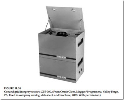
The GTS-300* test set is shown in Figure 11.36. The test connections for conducting this test are shown in Figure 11.37.
The below listed guidelines are offered when using the high-current method of testing the continuity of ground grids and grounds. However, it should be kept in mind that these are only guidelines since each ground has to be considered on its own merits relative to other grounds in the immediate vicinity.
1. The voltage drop of the ground grid rises approximately 1 V for each 50 ft of straight distance from the reference point.
2. On equipment with single ground the ground can be considered satisfactory if the voltage drop is in line with item 1 above and at least 200 A flow to the ground conductor under test into the grid. On most equipment of this type, 300 A will flow to the grid; however, in some cases current will also flow through foundation bolts and or conduits.
3. On equipment with multigrounds, a ground can be considered satisfactory if the voltage drop is in line with item 1 above and at least 150 A flow to the ground conductor under test into the grid. If the current to the grid is less than 150 A, the ground should be disconnected from the equipment and 300 A again should be passed through the ground. If the ground passes the 300 A and the voltage drop does not increase more than 0.5 V over the previous level, the ground can be considered satisfactory.
“Caution: Before any ground is removed from an equipment be sure to parallel it with a 2/0 CU temporary ground, such as a truck ground or other grounds before it is disconnected.”
4. To test transformer neutral or reference point pass 300 A through the transformer neutral at a point above grade but below any bonding connections or clamps on the tank. If at least 150 A flow to the ground grid, the reference point can be considered satisfactory.
5. Establish a reference ground, preferably a transformer neutral. From a high-current AC source (GTS-300) connect one test lead to ground being tested as shown in Figure 11.37. Connect the test lead at a point above grade but below the bonding connections or clamps. Pass 300 A through the ground grid and record the voltage drop across the grid. Using a clip-on ammeter, measure the amount of test current flowing above (to the equipment) and below (to the grid) the test lead on the ground being tested. The voltage drop should be in accordance with item 1 above. The test amperes should be in accordance with items 2 and 3 in this list.

