Switches
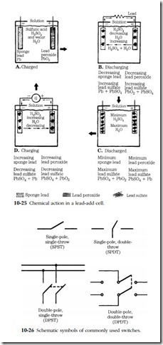
Switches neither add energy to the circuit nor take it out. Their function is to give flexibility by making or breaking circuits or by providing alternate current paths. They are classified by the number of poles (movable contacts) and throws (closed positions). Figure 10-26 illustrates four standard switch types in schematic form.
A single-pole, single-throw switch is like an ordinary light switch in that it makes and breaks a single circuit with one movement from the rest position. Single-pole, double-throw (SPDT) switches have three terminals, but control a single circuit with each throw. As one is completed, the other is opened. You can visualize an SPDT as a pair of SPST switches in tandem. Double-pole, double-throw switches control two circuits with a single movement. Think of the DPDT as two DPST switches com- bined, but working so that when one closes the other opens.
Self-actuating switches
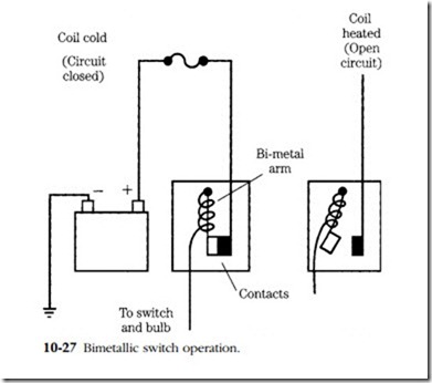
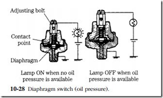
Not all switching functions are done by hand. Some are too critical to trust to the operator’s alertness. In general two activating methods are used. The first depends on the effect of heat on a bimetallic strip or disc to open or close contacts. Heat can be generated through electrical resistance or, as is more common, from, the engine coolant. The bimetallic element consists of two dissimilar metals bonded back-to-back. Because the coefficient of expansion is different for the metals, the strip or disc will deform inward, in the direction of the least expansive metal. Figure 10-27 illustrates this in a flasher unit. Other switches operate by the pressure of a fluid acting against a diaphragm. The fluid can be air, lube oil, or brake fluid. The most common use of such switches is as oil pressure sensors (Fig. 10-28).
Relays
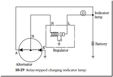
Relays are electrically operated switches. They consist of an electromagnet, a movable armature, a return spring, and one or more contact sets. Small currents excite the coil, and the resulting magnetic field draws the armature against the coil.
This linear movement closes or opens the contacts. The attractiveness of relays is that small currents—just enough to excite the electromagnet—can be used to switch large currents. You will find relays used to activate charging indicator lamps (Fig. 10-29), some starter motors, horns, remotely controlled air trips, and the like.
Solenoids are functionally similar to relays. The distinction is that the movable armature has some nonelectrical chore, although it might operate switch contacts in the bargain. Many starter motors employ a solenoid to lever the pinion gear into engagement with the flywheel. The next chapter discusses several of these starters.
Circuit protective devices
Fuses and fusible links are designed to vaporize and open the circuit during overloads. Some circuits are routed through central fuse panels. Others can be pro- tected by individual fuses spliced into the circuit at strategic points.
Fusible links are appearing with more frequency as a protection for the battery- regulator circuit (Fig. 10-30). Burnout is signaled by swollen or discolored insulation over the link. New links can be purchased in bulk for soldered joints, or in precut lengths for use with quick-disconnects. Before replacing the link, locate the cause of failure, which will be a massive short in the protected circuit.
On the other hand, a blown fuse is no cause for alarm. Fuses fatigue and become resistive with age. And even the best-regulated charting circuit is subject to voltage and current spikes, which can take out a fuse but otherwise are harmless. Chronic failure means a short or a faulty regulator.
Capacitors (condensers)
Two centuries ago it was thought that Leyden jars for storing charges actually condensed electrical “fluid.” These glass jars, wrapped with foil on both the inner and outer surfaces, became known as condensers. The term lingers in the vocabulary of automotive and marine technicians, although capacitor is more descriptive of the devices’ capacity for storing electricity.
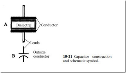
A capacitor consists of two plates separated by an insulator or dielectric (Fig. 10-31). In most applications the plates and dielectric are wound on each other to save space.
A capacitor is a kind of storage tank for electrons. In function it is similar to an accumulator in hydraulic circuits. Electrons are attracted to the negative plate by the close proximity of the positive plate. Storing the electrons requires energy, which is
released when the capacitor is allowed to discharge. Shorting the plates together sends free electrons out of the negative plate and to the positive side. There is a to- and-fro shuttle of electrons between the plates until the number of electrons on the plates is equalized. The number of oscillations depends on circuit resistance and reactance (or the reluctance of the capacitor to charge because of the mutual repul- sion of electrons on the negative plate).
Capacitors block direct current, but pass alternating current. The electrons do not physically penetrate the dielectric. The distortions in the orbits of the electrons in the dielectric displace or attract electrons at the plates. The effect on alternating current in a circuit is often as though the dielectric did not exist at least at the higher frequencies.
Capacitors are found at the generator or alternator, where they shunt high- frequency alternating current to ground to muffle radio interference.
