Direct and alternating current
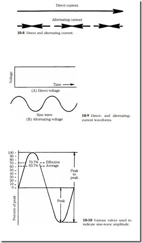
Diesel engines might employ direct or alternating currents. The action of direct, or unidirectional, current can be visualized with the aid of the top drawing in Fig. 10-8. Alternating current is expressed by the opposed arrows in the lower drawing. Flow is from the negative to the positive poles of the voltage source, but the poles exchange identities, causing the current reversal. The positive becomes negative, and the negative becomes positive.
The graph in Fig. 10-9 represents the rise, fall, and reversal of alternating current. Because the amplitude changes over time, alternating voltage and current values require some qualification. The next drawing illustrates the three values most often used.
Peak-to-peak values refer to the maximum amplitude of the voltage and amperage outputs in both directions. In Fig. 10-10 the peak-to-peak value is 200 Vp-p (or 200 Ap-p). The half-cycle (alternation) on top of the zero reference line is considered to be positive; below the line alternation is negative.
The root mean square (rms) value is sometimes known as the effective value. One rms ampere has the same potential for work as 1-A direct current. Unless oth- erwise specified, alternating current values are rms (effective) values and are directly comparable to direct current in terms of the work they can do. Standard meters are equipped with appropriate scales to give rms readings.
The illustration depicts one complete cycle of alternating current. The number of cycles completed per second is the frequency of the current. One cycle per second is the same as one hertz (1 Hz). Domestic household current is generated at 60 Hz. The alternating current generators used with diesel engines are variable-frequency devices because they are driven by the engine crankshaft. At high speed a typical diesel alternating current generator will produce 500–600 Hz.
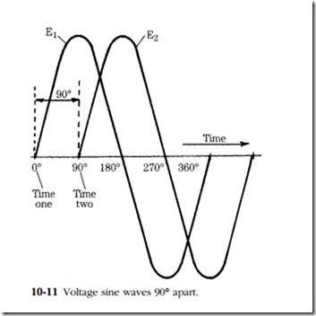
In addition to these special characteristics, alternating current outputs can be superimposed upon each other (see Fig. 10-11). The horizontal axis (X-axis) repre- sents zero output—it is the crossover point where alternations reverse direction. In this particular alternator 360° of rotation of the armature represents a complete out- put cycle from maximum positive to maximum negative and back to maximum positive. The X-axis can be calibrated in degrees or units of time (assuming that the alternator operates at a fixed rpm). Note that there are two sine waves shown. These waves are out of phase; E1 leads E2 by 90° of alternator rotation. Alternators used on diesel installations usually generate three output waves 120° apart. Multiphase outputs are smoother than single-phase outputs and give engineers the opportunity
to build multiple charging circuits into the alternator. Circuit redundancy gives some assurance against total failure; should one charging loop fail, the two others continue to function.


