Circuits
The term circuit comes from a Latin root meaning circle. It is descriptive because the path of electrons through a conductor is always in the form of a closed loop, bringing them back where they started.
A battery or generator has two terminals, or posts. One terminal is negative. It has a surplus of electrons available. The other terminal has a relative scarcity of elec- trons and is positive.
A circuit is a pathway between negative and positive terminals. The relative ease with which the electrons move along the circuit is determined by several factors. One of the most Important is the nature of the conductor. Some materials are better conductors than others. Silver is at the top of the list, followed by copper, aluminum, iron, and lead. These and other conductors stand in contrast to that class of materials known as insulators. Most gases, including air, wood, rubber, and other organic materials, most plastics, mica, and slate are insulators of varying effectiveness.
Another class of materials is known as semiconductors. They share the characteristics-of both conductors and insulators and under the right conditions can act as either. Silicon and germanium semiconductors are used to convert alternating current (AC) to direct current (DC) at the alternator and to limit current and voltage outputs. These devices are discussed in more detail later in this chapter.
The ability of materials to pass electrons depends on their atomic structures. Electrons flood into the circuit from the negative pole. They encounter other elec- trons already in orbit. The newcomers displace the orbiting electrons (like repels like) toward the positive terminal and, in turn, are captured by the positive charge on the nucleus (unlike attracts). This game of musical chairs continues until the cir- cuit is broken or until the voltages on the terminals equalize. Gold, copper, and other conductors give up their captive electrons with a minimum of fuss. Insulators hold their electrons tightly in orbit and resist the flow of current.
You should not have the impression that electrons flow through various sub- stances in a go/no-go manner. All known materials have some reluctance to give up their orbiting electrons. This reluctance is lessened by extreme cold, but never reaches zero. And all insulators ‘leak’ to some degree. A few vagrant electrons will pass through the heaviest, most inert insulation. In most cases the leakage is too small to be significant. But it exists and can be accelerated by moisture saturation and by chemical changes in the insulator.
Circuit characteristics
Circuits, from the simplest to the most convoluted, share these characteristics:
• Electrons move from the negative to the positive terminal. Actually the direction of electron movement makes little difference. In fact, for many years it was thought that electrons moved in the opposite direction—from positive to negative.
• The circuit must be complete and unbroken for electrons to flow. An incomplete circuit is described as open. The circuit might be opened delib- erately by the action of a switch or a fuse, or it might open of its own accord as in the case of a loose connection or a broken wire. Because cir- cuits must have some rationale besides the movement of electrons from one pole to the other, they have loads, which convert electron movement into heat, light, magnetic flux, or some other useful quantity. These working ele- ments of the circuit are also known as sinks. They absorb, or sink, energy and are distinguished from the sources (battery and the generator). A circuit in which the load is bypassed is described as shorted. Electrons take the easiest, least resistive path to the positive terminal.
• Circuits can feed single or multiple loads. The arrangement of the loads determines the circuit type.
Series and parallel circuits
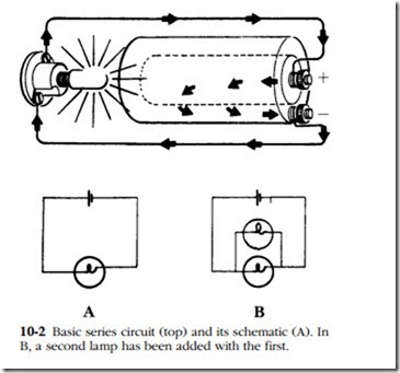
A series circuit has its loads connected one after the other like beads on a string (Fig. 10-2A). There is only one path for the electrons between the negative and pos- itive terminals. In a string of Christmas tree lights, each lamp is rated at 10V; 11 in. series required 110V. If any lamp failed, the string went dark.
Pure series circuits are rare today. (They can still be found as filament circuits in some AC/DC radios and in high-voltage applications such as airport runway lights.) But switches, rheostats, relays, fuses, and other circuit controls are necessarily in series with the loads they control.
Parallel circuits have the loads arranged like the rungs of a ladder, to provide multiple paths for current (Fig. 10-2). When loads are connected in parallel, we say they are shunt. Circuits associated with diesel engines usually consist of parallel loads and series control elements. The major advantage of the parallel arrangement from a serviceman’s point of view is that a single load can open without affecting the other loads. A second advantage is that the voltage remains constant throughout the network.
Single- and two-wire circuits
However the circuit is arranged—series, parallel, or in some combination of both—it must form a complete path between the positive and negative terminals of the source. This requirement does not mean the conductor must be composed entirely of electrical wire. The engine block, transmission, and mounting frame are not the best conductors from the point of view of their atomic structures. But because of their vast cross-sectional area, these components have almost zero resistance.
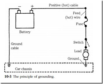
In the single-wire system the battery is grounded, or as the British say, earthed (Fig. 10-3). These terms seem to have originated from the power station practice of using the earth as a return. With the exception of some Lucas and CAV systems, most modem designs have the negative post grounded. The ‘hot’ cable connects the pos- itive post to the individual loads, which are grounded. Electrons flow from the negative terminal, through the loads, and back to the battery via the wiring.
The single-wire approach combines the virtues of simplicity and economy. But it has drawbacks. Perhaps the most consequential is the tendency for the connections to develop high resistances. One would think that a heavy strap bolted to the
block would offer little resistance. Unfortunately this is not the case. A thin film of oil, rust, or a loose connection is enough to block the flow of current.
Corrosion problems are made more serious by weather exposure and electrolysis. Electrolysis is the same phenomenon as occurs during electroplating. When current passes through two dissimilar metals (e.g., copper and cast iron) in the presence of damp air, one of the metals tends to disintegrate. In the process it undergoes chemical changes that makes it a very poor conductor.
Another disadvantage of the single-wire system, and the reason it is not used indiscriminately on aircraft and ocean-going vessels, is the danger of short circuits. Contact between an uninsulated hot wire and the ground will shunt the loads down circuit.
The two-wire system (one wire to the load, and a second wire from it to the pos- itive terminal) is preferred for critical loads and can be used in conjunction with a grounded system. Electrolytic action is almost nil, and shorts occur only in the unlikely event that two bare wires touch.

