This chapter investigates the thermal stress of wind power converter when suffering from grid faults. The comprehensive analysis for the electrical and thermal behaviors of power devices undergoing various grid faults is conducted on the 3L-NPC wind power converter. Afterwards, a series of thermal-redistributed modulation methods and a power control strategy which utilizes the zero sequence current are presented to achieve better performance under this adverse condition.
Requirements and Conditions Under Fault Operation
Besides the normal operation, the TSOs in different countries have also issued strict Low Voltage Ride Through (LVRT) codes for the wind turbine system, as shown in Fig. 1.10. Meanwhile, it is becoming a need that the wind power generation system should be able to provide reactive power (up to 100 % current capacity) to con- tribute to the voltage recovery when grid faults are present. Figure 1.11 shows the required amount of reactive current against to the lowest grid voltage amplitude regulated by German grid codes. As a case study, the German LVRT codes are adopted in this chapter for analysis, and the same 3L-NPC wind power converter model as already illustrated in Sect. 4.1 is again used to demonstrate the converter behavior under various grid fault conditions. However, in this chapter, only the grid-side converter is focused.
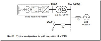
When a short-circuit fault happens in the power grid, depending on the types and location of fault, the line impedances, and the connection of transformer windings, the voltage dips may vary significantly on different locations (buses) in the power grid system [1, 2]. Therefore, it is important to investigate how the voltage dips propagate to the bus where the WTS is connected. A typical configuration of a WTS with the grid system is shown in Fig. 5.1, in which the voltage on Bus 2 is monitored by the WTS and hence determines the LVRT behavior of the wind power converter. A delta-star transformer is used to interface the WTS on Bus 2 (e.g., 3.3 kV) and the Point of Common Coupling (PCC) on Bus 1 (e.g., 20 kV). It is assumed that a short-circuit fault happens somewhere with line impedance ZF to
Define that the voltage dip severity on Bus N is DN, which is related to the location of grid faults and power line impedance. Providing that the line impedances for the positive and negative sequence components are equal, the dip severity on the Point of Common Coupling (or Bus 1) D1 can be written as [2]
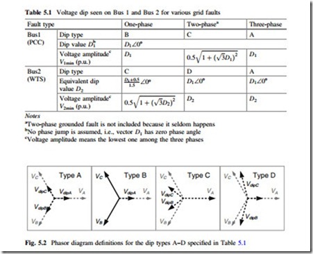
It is obvious that D1 ranges from 0 (if ZF = 0) to 1 (if ZS = 0) and represents the voltage dipping severities from the most severe case (D1 = 0) to the non-dip case (D1 = 1). Three typical grid faults, one-phase grounded (1 phase), two-phase connected (2 phase), and three-phase grounded (3 phase), are assumed to happen, respectively, at the same location of the given power grid system. The dip type, dip severity, and voltage amplitude of the three faults seen on Bus 1 and Bus 2 are summarized in Table 5.1, where the voltage dipping type is defined in Fig. 5.2 [1]. It is noted that the voltage dipping characteristics appeal differently not only among the three types of grid faults, but also among different buses. Because Bus 2 is directly connected and monitored by the WTS, only V2min will determine the amount of reactive current injection into the power grid by the converter when the three types of grid faults are present.
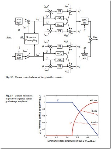
Figure 5.3 shows the control scheme adopted to deal with unbalanced grid faults: both positive and negative sequences voltages/currents are detected and controlled. A sequence decoupling algorithm is used to remove the 100 Hz oscillation components in each of the sequence domain [2–5]. It is worth to mention that the current control schemes of wind power converter under grid faults may have strong impacts to the loading of power devices, but this is still an open question under discussion because the definitions for the current and voltage behaviors of each phase under grid faults have not yet been clearly specified. In this section, it is first assumed that only positive sequence currents are generated by the converter, and the negative sequence currents are control to be zero by setting the references for negative sequence currents to zero when using the control method shown in
Fig. 5.3. The current references in positive sequence for converter as a function of the minimum grid voltage amplitude are specified in Fig. 5.4, where the reactive
current Iq is set according to Fig. 1.11, and the active current Id is referred to the generated power by wind turbines when V2min is above 0.5 p.u. It is assumed that the converter is set to provide as much active power as possible during grid faults, and the pitch control of the wind turbine does not have enough time to activate [6]. This is the worst LVRT condition for the power converter in terms of device loading.
The 10 % increased DC bus voltage of converter is taken into account in the stress analysis under LVRT, and this is due to the short-term input–output power unbalance and the trigging of DC bus chopper [6]. It is noted that the increased DC bus voltage may significantly decrease the lifetime of power switching devices due to the cosmic radiation failure mechanism as reported in [7]. However, this issue will not be considered in this book.


