Stator Condition
When discussing the stator, we are referencing the DC or three-phase AC windings, insulation between the turns of the winding, solder joints between the coils, and the stator core or laminations. This fault zone creates a lot of debate as to the cause and rate of failure. The stator fault zone is
often considered one of the most controversial areas due to the significant challenge in early fault detection and the prevention of motor failure surrounding the stator windings. This challenge is further intensified in higher voltage machines, where the fault-to-failure time frame becomes much shorter. The stator fault zone is identified as the health and quality of the insulation between the turns and phases of the individual turns and coils inside the motor.
Failure Mechanisms
The likely mechanisms of a stator-winding fault are either a turn-to-turn, phase-to-phase, or turn-to-ground short. A turn-to-turn short is identified as a short of one or more windings in a coil. This can develop into a very low impedance loop of wire, which acts as a shorted secondary of a current transformer. This results in excessive current flow through the shorted loop, creating intense heat and insulation damage. Due to the nature of a random wound design, a shorted turn could occur with much higher impedance, allowing the motor to run for extended periods of time before eventually destroying the coil with the high currents. As a result, it is not unusual to find random wound motors still running with bad stator windings. Form-wound coils however, do not exhibit high turn impedances and will there- fore heat up quickly following the presence of a turn-to-turn short. A phase-to-phase short is identified as a short of one or more phases to another phase. This fault can be quite damaging due to the possibility of very large voltage potential existing between phases at the location of the short.
Analysis
The big controversy, which surrounds the stator fault zone, is whether technology can give ample warning of an impending stator-winding failure.
A motor will develop a turn-to-turn, phase-to-phase, or ground short over
its life. The goal of any test, when faced with this type of long-term certainty, is to identify the impending conditions, which may be conducive to these faults, so the condition can be corrected. If the conditions conducive to faults are removed, then a longer life for the motor can be expected. If a turn- to-turn short has occurred, then preventing a restart of the motor may be the best thing at that point in the troubleshooting effort. Again, if you wait until the turn-to-turn short has occurred before you test the motor, you have waited too long.
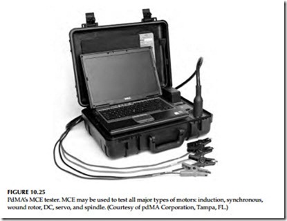
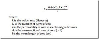
A surge comparison test set, or PdMA’s MCE test instrument, shown in Figure 10.25, applies a high-frequency AC signal and a low-voltage DC signal to the stator windings to perform stator analysis. From these signals, inductance and resistance measurements are taken for comparison between like coils and historical data. When testing a three-phase AC induction motor, comparison between the three phases is the most powerful tool. When test- ing a DC motor, only a single phase exists and comparison to historical test data or identical motors would be effective. Inductance is a highly sensitive parameter and is influenced by many variables within the motor. Rotor con- dition, air gap flux, frame construction (iron or aluminum), and winding condition are a few of the variables. The most influential variable on the inductance reading is the winding condition. Specifically the number of turns is a squared value in the overall inductance equation as seen below:
Although it is our goal to prevent a turn-to-turn short from occurring, you can see that a loss of a single turn in a stator winding will have a dramatic effect on the overall inductance of one or more phases based on the coil con- figuration. In our effort to identify the conditions that are conducive to a turn-to-turn short, we can use other variables in the equation to identify anomalies, which could create stator problems.
Stator faults often end up as a turn-to-turn short, but begin as something else. An example is a motor with excessive vibration, which results in winding movement, friction, and eventually worn insulation between the winding turns. Another example is rotor defects, which create intense heat on the winding surface and eventually create weakened turn insulation or even a ground fault. Core iron defects, such as shorted laminations, will also create additional heat, airflow disturbance, and elevated vibration due to imbalanced magnetic fields and air gap flux. What influence do these situations have on stator inductance? Other than vibration, rotor defects and air gap flux anomalies have a direct impact on the permeability ( m) of the stator windings. Changes in m due to a stator core defect will create changes in inductance related to a specific group of coils located near the defect. Changes in m due to rotor defects will have a varying influence on the stator inductance as the rotor position changes. A quick comparison of the inductance and inductive imbalance values between the three phases or to historical data will indicate changes in these variables and prompt further action or testing to be performed in an effort to prevent the turn-to-turn short.
Stator analysis may be performed by evaluating the phase relationship of voltage and current for each of the three phases of an AC induction motor. These values are used to determine the impedance of each phase and dis- play them as an impedance imbalance. Any change in the real or reactive component of one phase that is not duplicated on another phase will indicate a change that needs to be investigated. One of the hurdles involved in this type of testing is acquiring this dynamic data at a load substantial enough to allow these values to be affected by the condition of the windings and not the design. An unloaded motor may run with a current imbalance. This creates variations in the phase impedance, which duplicates indications of a stator fault. Therefore, it is important to have approximately 70% load or more to remove the design impact on these values. Testing should not stop at <70% load, but you must use the test data as comparison values only.
A test today at 50%–60% load compared to a test last quarter at 50%–60% load is still a very informative test. The more test points are obtained, the more confidence there is in the condition of your stator windings.
Another application is the ability to acquire data on current through the start-up cycle of the motor. The motor is under the most stress during start-up and can give many indications of problems existing or developing. Stator defects, as in open or shorted turns, will be identified as a change in the amplitude of the inrush current. The inrush current is the highest amplitude of current seen through a start-up and occurs immediately after the motor is energized. This occurs due to the effective locked rotor condition, which the motor is in at start-up. Without rotor movement, the counter electromotive force created by the rotor to reduce current flow in the stator does not exist. In fact, the inrush current immediately following the start of a motor is not affected by load at all. Whether at full load or no load during a start-up, the inrush current will be the same. Only line voltage and circuit impedance will have an effect on the inrush current. The current, which exists following the initial inrush however, is greatly affected by the load. If only line voltage and circuit impedance will affect the inrush current value and we generally expect line voltage to be the same, we must rely on circuit impedance as an indicator of stator health. Inrush current is dependent on impedance of the circuit therefore increased inrush current from normal indicates lower circuit impedance. Lower circuit impedance could be caused by weakened turn insulation or shorted turns and an open winding, high resistance connection or even incorrect repair specifications may cause higher circuit impedance. If significant temperature variations occur from one test to another, it will have an impact on the overall circuit impedance. The effect of temperature should be considered when evaluating the start-up data including inrush current.
It is important to remember that stator defects do not exist very long before they can become catastrophic. Use all the tools available, know the circumstances, and act quickly to dismiss or confirm stator fault indications. The goal of stator analysis is to identify any condition that may lead to a turn- to-turn short so that condition can be corrected before a turn-to-turn short occurs. If turn-to-turn shorts go undetected, then over time they will become bigger faults, such as coil-to-coil short, or phase-to phase short. Refer to Section 10.11.9 on surge comparison tests for detecting turn-to-turn shorts.


