HYDROPOWER TURBINES
The most important mechanical component of any hydropower-generating unit is its turbine. This is the device that converts the energy contained in the moving water into the rotary motion necessary to turn a generator and produce electric- ity. The hydraulic turbine is a simple, reliable, and well-understood component made from simple materials. Most turbines are made from iron or steel or cast from bronze or other alloys. In the past wood was commonly used too.
The history of the hydropower turbine is long. The earliest known, water wheels for grinding grain, were used by the Romans and were known in China in the 1st century. They were common across Europe by the 3rd century and could be found in Japan by the 7th century. The Doomsday Book of AD1086 records 5000 in use in the south of England. These early water wheels were made of wood. Iron was first used in the 18th century by an English engineer, John Smeaton.
Early water wheels were simple paddle wheels, the lower edge of which was placed into a flowing stream where the pressure of water against one side of the immersed paddle caused it to turn. This is the basis for one group of turbines in use today called reaction turbines. It was later discovered that more energy could be extracted by damming the water to create a head and using the pressure at the bottom of this head to create a jet of water that was directed against the paddles of the wheel. This principle led to the development of the second main branch of hydropower turbines, the impulse turbines.
Modern turbines can be extremely efficient with the best converting 95% of the energy contained in the water into rotary motion. They can be stopped and started very quickly and are capable of operating reliably for many years. Large
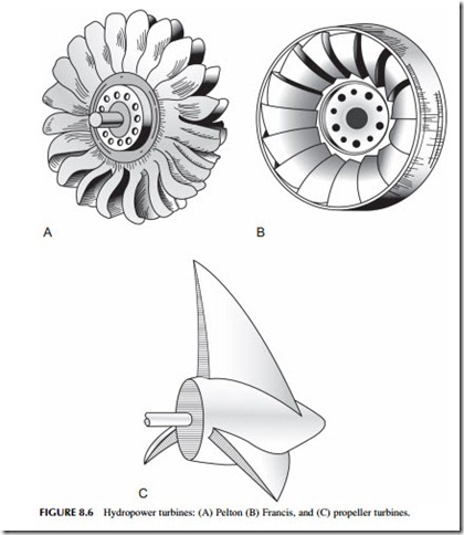
hydropower projects generally make use of one of a small number of turbine types, discussed in the following sections (Figure 8.6). Small hydropower plants utilize these same types but they can exploit a wider range of turbines including some extremely novel designs (see later).
Impulse Turbines
A tall column of water creates a high pressure at its base and if the water under high pressure is released through a fine nozzle it will create a high-speed jet of water. If this jet is directed onto a bucket-shaped paddle on a wheel it will
generate an impulse that causes the wheel to turn. This is the basis for the impulse turbine.
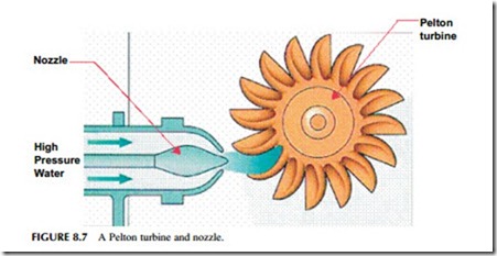
The main type of impulse turbine in use today is the Pelton turbine, patented by the American engineer Lester Allen Pelton in 1889 (Figure 8.7). The Pelton turbine operates at its highest efficiency, 95%, when the speed of movement of the bucket on the wheel rim is half that of the water in the jet directed into it.
The Pelton turbine is generally used where a high head of water is available and the flow rate is low. For large hydropower plants they are normally pre- ferred when a head height of more than 450 m is available, but they can be used for heads a low as 200 m. The maximum head for a single Pelton turbine is normally 1000 m. Beyond that the fall must be divided into two sections and more than one turbine will be required.
A simple Pelton turbine will have one nozzle but power output can be increased by using up to four nozzles directed at the same wheel. Most Pelton turbines are mounted vertically with a horizontal axis of rotation, but they can be mounted with a vertical axis so that the turbine lies horizontally. A key feature of all Pelton turbines is that they must operate in free air, not submerged. The turbine must, therefore, always be positioned above the water level at the bottom of the head of water being utilized for power generation.
The speed at which a Pelton turbine rotates will be determined by both the flow rate of water directed into its buckets and the load into which it is feeding. If the load falls, the turbine will speed up. This can be controlled by reducing flow through the nozzles. The optimum efficiency is achieved when the turbine is operating between 60% and 80% of maximum load.
A second type of impulse turbine available for high-head use is the Turgo turbine. This is similar to the Pelton in design, but whereas with the Pelton turbine the water jets are in the same plane as the turbine wheel, in the Turgo tur- bine the jet strikes each bucket from one side and then exits the turbine at the
other side. The Turgo turbine can handle higher flow rates than the Pelton but is generally more difficult to construct. It is normally used for medium-head applications between those best suited to the Pelton and those more suited to reaction turbines.
Reaction Turbines
For heads of water below 450 m, a reaction turbine will normally be the first choice. This type of turbine must be completely submerged to operate efficiently. Whereas the impulse turbine harnesses the kinetic energy (and the momentum carried by its mass) of a jet of high-pressure water, a reaction turbine responds to the pressure (potential energy) created by the weight of water at the base of the head acting on one side of its blades.
There are several different types of reaction turbine. The most popular, accounting for 80% of all hydraulic turbines in operation, is the Francis turbine. This can be used in almost every situation, but for very low heads, propeller turbines and Kaplan turbines are frequently preferred.
Francis Turbine
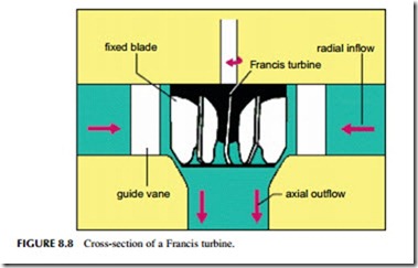
The Francis turbine was developed by James Bichens Francis around 1855. Its key characteristic is the fact that water changes direction as it passes through the turbine. The flow enters the turbine in a radial direction, flowing toward its axis, but after striking and interacting with the turbine blades it exits along the direction of that axis (Figure 8.8). It is for this reason that the Francis turbine is some- times called a mixed-flow turbine. For it to operate efficiently, water must reach
radial inflow Francis turbine
axial outflow
all blades equally and flow is controlled by a set of valves or gates that curl around the turbine itself in a spiral shape.
The blades of a Francis turbine are carefully shaped to extract the maximum amount of energy from the water flowing through it. Water should flow smoothly through the turbine for best efficiency. The force exerted by the water on the blades causes the turbine to spin and the rotation is converted into electricity by a generator. Blade shape is determined by the height of the water head available and the flow volume. Each turbine is designed for a specific set of conditions experienced at a particular site. When well designed, a Francis turbine can capture 90–95% of the energy in the water.
The Francis design has been used with head heights from 3 m to 600 m, but it delivers its best performance between 100 m and 300 m. Flow rate is often the limiting factor for a given head. As the head height rises, the size of the turbine must fall, making fabrication more difficult. High-head Francis applications, therefore, require a large flow to be successful. Conversely, for low-head appli- cations the flow must be low or the turbine will become excessively large. It is for this reason that while the Francis turbine is the most versatile, different designs are generally used for both very high and very low heads.
Francis turbines are also the heavyweights of the turbine world. The largest, found at both the Itaipu power plant on the Brazil–Paraquay border and at the Three Gorges Dam in China, have generating capacities of 700 MW each.
Propeller and Kaplan Turbines
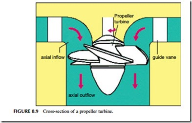
If the head of water becomes too low, the rotational speed of a Francis turbine falls and with it efficiency. For low-head applications an alternative turbine type is required and the most successful is the propeller turbine (Figure 8.9).
A propeller turbine looks like the screw of a ship, but its mode of operation is the reverse of the ship’s propulsion unit. In a ship a motor turns the propeller, which pushes against the water, forcing the ship to move. In the hydropower plant, by contrast, moving water drives the propeller turbine to generate power.
Propeller turbines are most useful for low-head applications such as slow- running, lowland rivers. The head of water is typically 10 m or less. Their efficiency drops off rapidly when the water flow drops below 75% of the design rating, so plant designers often use multiple propeller turbines in parallel, shut- ting down some when the water flow drops to keep the remaining turbines operating at their optimum efficiency.
A variant of the propeller turbine is the bulb turbine, used for extremely low- head conditions. In this design the turbine is integrated with a water-tight generator and enclosed in a bulb-shaped container. The turbine rotor can have fixed or variable blades. Water flows into one end of the bulb-shaped container, called the nacelle, and out the other, with no change of direction. The use of the nacelle helps concentrate the flow to maximize energy capture. The bulb turbine has been used in tidal power plants.
There are cases where multiple turbines cannot easily be used. In these cases, an alternative called the Kaplan turbine has sometimes been utilized instead. This low-head variant of the propeller turbine was developed by Viktor Kaplan in 1915. Its primary feature is a set of blades that can be adjusted to maximize efficiency under different flow conditions. These turbines can operate at higher flow levels than conventional propeller turbines and are suited to heads between 10 m and 50 m. A variation of the Kaplan turbine is the diagonal- flow turbine that can operate at higher rotational speeds than the Kaplan and is suited to higher heads.
Deriaz Turbine
A further turbine available to hydropower plant designers is the Deriaz turbine invented by Paul Deriaz. This has blade shapes similar to a Francis turbine but these blades are adjustable and so they can be adapted to different flow rates. The Deriaz turbine is another mixed-flow turbine in which water enters from the size but exits along the turbine axis. It is best suited to head heights between 20 m and 100 m, in between the ranges of Francis and Kaplan turbines.


