Testing for Ratio of Instrument Transformers
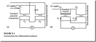
The ratio of instrument transformers can be determined by two generally accepted tests.
Voltage method test
A suitable AC voltage, below saturation i.e., below the knee point of the CT saturation curve, is connected to the full secondary winding and a high impedance (20,000 Ω/V or greater) low-range voltmeter is connected in the primary of the CT. The primary voltage is read on the low-range voltmeter as the secondary voltage is applied to the CT. The turn ratio is approximately equal to the voltage ratio. In most low and medium-ratio bushing CTs, the saturation level is achieved at about 1 V per turn. The saturation level may be lower than 0.5 V per turn in high-ratio generator CTs and window-type CTs used in metal clad switchgear. For very high-ratio CTs, an application of test voltage even lower than 0.5 V per turn may be required to avoid personnel hazard and possible damage to equipment.
Current method test
This method requires a source of high current and an additional CT of known ratio with its own ammeter and a second ammeter for the CT under test. The test is conducted by injecting the high current test source to a series of values over the desired range and recording the two secondary current readings.
The ratio of the CT under test is equal to the turns ratio of the reference CT multiplied by the ratio of the reference CT secondary current to the test transformer secondary current. When conducting this test avoid using multiple turns of the test conductor through the center of the window-type CT to reduce its ratio because it may produce an abnormal secondary leakage reactance and misleading results in the ratio measurement. The effect is unpredictable and although small with distributed winding CTs with low secondary burden, it may be produce a large error in older CTs particularly when high burdens are connected.
Excitation test
Excitation voltage and current tests can be made on both C (distributed winding) and T class (nondistributed winding) CTs in order to assess if the CT is performing correctly and to determine if deviations are present.
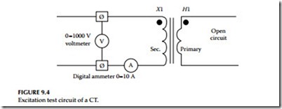
To perform this test, an AC voltage is applied to the secondary winding
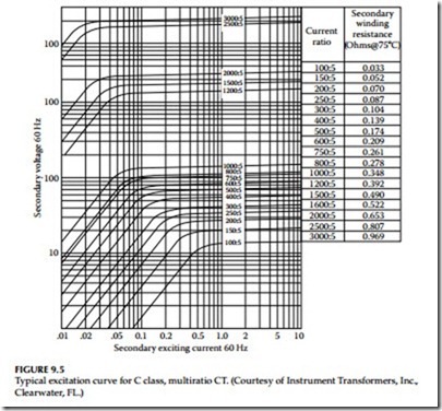
with the primary winding open-circuited as is shown in Figure 9.4. The voltage applied to the secondary winding is varied, and the current drawn by the winding at each selected voltage value is recorded. A curve is plot- ted of the secondary voltage versus current for comparison with the origi- nal manufacturer ’s excitation (saturation) curve. A sample of excitation curves of multiratio CT are shown in Figure 9.5. The readings near the
knee of the excitation curve are important when plotting this curve. For multitap ratio CTs, the highest tap should be used provided that the cur- rent transformer can be saturated at the selected tap with the test equipment available. The ammeter used for this test should be an root- mean-square (rms) instrument and the voltmeter should be an average reading voltmeter calibrated to give the same numerical indication as an rms voltmeter. Deviations from expected results or in comparison to the manufacturer data may indicate a turn-to-turn short, distorted wave- form of test voltage, or the presence of a conducting path around the CT core. Caution should be taken to minimize energizing the CT at voltages above the knee of the excitation curve any longer than is necessary to take the readings. This test can also be conducted by energizing the CT primary winding from a high-current test source and plotting the data as primary exciting current versus secondary open-circuited voltage. The current must be divided by the CT ratio for comparison with the manufacturer ’s excitation curve data.


