Overload Setting
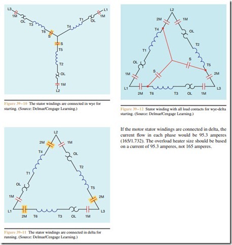
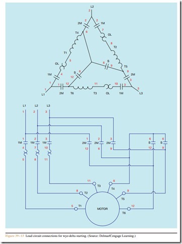
Notice in Figure 39 – 12 that the overload heaters are connected in the phase windings of the delta, not the line. For this reason, the overload heater rating must be reduced from the full load current rating on the motor nameplate. In a delta connection, the phase current will be less than the line current by a factor of the square root of 3, or 1.732. Assume, for example, that the nameplate indicates a full load current of 165 amperes.
Review Questions
1. Name two requirements that must be met before a motor can be used for wye-delta starting.
2. The stator windings of a 2300 volt motor have an impedance of 6 ohms when the motor is first started. What would be the in-rush current if the stator windings were connected in delta?
3. What would be the amount of in-rush current if the motor described in question #2 had the stator windings connected in wye?
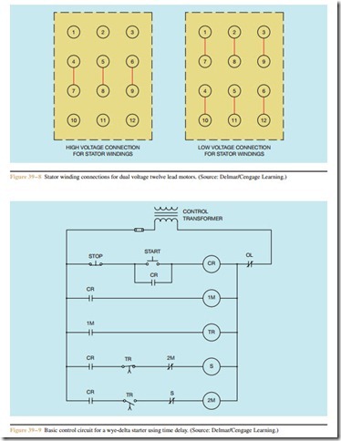
4. Refer to the circuit shown in Figure 39 – 9. Assume that timer TR is set for a delay of 10 seconds. When the Start button is pressed, the motor starts with its windings connected in wye. After a period of one minute, the motor has not changed from wye to delta. Which of the following could cause this condition?
a. TR timer coil is open.
b. S contactor coil is open.
c. 1M starter coil is open.
d. The control transformer fuse is blown.
5. Refer to the circuit shown in Figure 39 – 9. As- sume that timer TR is set for a delay of 10 seconds. When the Start button is pressed, the motor does not start. After a delay of 10 seconds, the motor suddenly starts with its stator windings connected in delta. Which of the following could cause this problem?
a. TR timer coil is open.
b. 2M contactor coil is open.
c. S contactor coil is open.
d. 1M starter coil is open.
6. Refer to the circuit shown in Figure 39 – 9. What is the purpose of the normally closed 2M and S contacts in the schematic?
7. The motor nameplate of a wye-delta starter motor has a full load current of 287 amperes. What current rating should be used to determine the proper overload heater size?
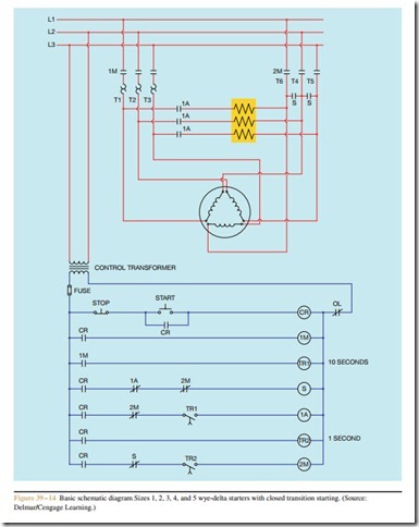
8. Refer to the circuit shown in Figure 39 – 14.
When the motor changes from wye to delta, what causes contactor coil S to de-energize and open S contacts?
9. Refer to the circuit shown in Figure 39 – 14. What is the purpose of timer TR2?
10. Refer to the circuit shown in Figure 39 – 14. When the Start button is pressed, the control transformer fuse blows immediately. Which of the following could not cause this problem?
a. Control Relay coil CR is shorted.
b. Starter coil 1M is shorted.
c. Contactor coil S is shorted.
d. Contactor coil 2M is shorted.


