Objectives
After studying this unit, the student will be able to:
• Discuss the differences between junction transistors and unijunction transistors
• Describe the operation of the unijunction transistor (UJT)
• Identify the leads of a UJT
• Draw the schematic symbol for a UJT
• Test a UJT with an ohmmeter
• Connect a UJT in a circuit
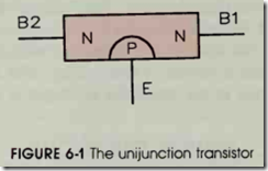
The unijunction transistor ( UJT) is a special transistor that has two bases and one emitter. The unijunction transistor is a digital device because it has only two states, on and off. It is generally clas sified with a group of devices known as thyristors. Thyristors are devices that are turned completely on or completely off. Thyristors include such de vices as the SCR, the triac, the diac and the UJT. The unijunction transistor is made by com bining three layers of semiconductor material as shown in figure 6-1. Figure 6-2 shows the sche matic symbol of the UJT with polarity connec
tions and the base diagram.
Current flows in two paths through the UJT. One path is from base #2 to base # 1. The other path is through the emitter and base # 1. In its normal state, current does not flow through either path until the voltage applied to the emitter is about 10 volts higher than the voltage applied to base # 1. When the voltage applied to the emitter is about 10 volts higher than the voltage applied to base # 1, the UJT turns on and current flows through the base # 1-base #2 path and from the emitter through base # 1. Current will continue to flow through the UJT until the voltage applied to the emitter drops to a point that is about 3 volts higher than the voltage applied to base # 1. When the emitter voltage drops to this point, the UJT will turn off and will remain off until the voltage applied to the emitter again reaches a level about
10 volts higher than the voltage applied to base #1.
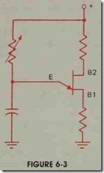
The unijunction transistor is generally con nected to a circuit similar to the circuit shown in figure 6-3. The variable resistor controls the ca pacitor’s rate of charge time. When the capacitor has been charged to about 10 volts, the UJT turns on and discharges the capacitor through the emit ter and base# 1. When the capacitor has been dis charged to about 3 volts, the UJT turns off and permits the capacitor to begin charging again. By varying the resistance connected in series with the capacitor, the amount of time needed for charging the capacitor can be changed, thereby controlling the pulse rate of the UJT (T = RC).
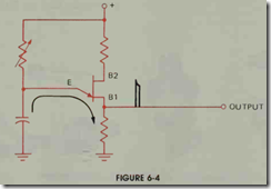
The unijunction transistor can furnish a large output pulse because the output pulse is produced by the discharging capacitor, figure 6-4. This large output pulse is generally used for triggering the gate of a silicon-controlled rectifier.
The pulse rate is determined by the amount of resistance and capacitance connected to the emitter of the UJT. However, the amount of ca pacitance that can be connected to the UJT is lim ited. For instance, most UJTs should not be con nected to capacitors larger than 10 J.LF because the UJT may not be able to handle the current spike produced by a larger capacitor, and the UJT could be damaged.
The unijunction transistor can be tested with an ohmmeter in a manner very similar to that used to test a common junction transistor. (For an ex-planation of how to test a unijunction transistor,
see Procedure 3 in the Appendix.)
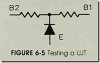
When testing the UJT with an ohmmeter, the UJT will appear as a circuit containing two resis tors connected in series with a diode connected to the junction point of the two resistors as shown in figure 6-5. If the positive lead of the ohmmeter is connected to the emitter of the UJT, a circuit should be seen between emitter and base 1 and emitter and base 2. If the negative lead of the ohmmeter is connected to the emitter, no circuit should be seen between the emiter and either base. If the ohmmeter leads are connected to the two bases, continuity will be seen between these two leads provided that the output voltage of the ohmmeter is hi’gh enough.
REVIEW QUESTIONS
1. What do the letters UJT stand for?
2. How many layers of semiconductor material are used to construct a UJT?
3. Briefly explain the operation of the UJT.
4. Draw the schematic symbol for the UJT.
Briefly explain how to test a UJT with an ohmmeter.


