SHADED-POLE MOTORS
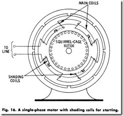
A shaded-pole motor is a single-phase induction motor equipped with an auxiliary winding displaced magnetically from, and connected in parallel with, the main winding. This type of motor is manufactured in fractional-horsepower sizes, and is used in a variety of household appliances, such as fans, blowers, hair driers, and other applications requiring a low starting torque. It is operated only on alternating current, is usually nonreversible, is low in cost, and is extremely rugged and reliable. The diagram of a typical shaded-pole motor is shown in Fig. 16.
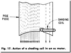
The shading coil (from which the motor has derived its name) consists of low-resistance copper links embedded in one side of each stator pole, which are used to provide the necessary starting torque. When the current increases in the main coils, a current is induced in the shading coil. This current opposes the magnetic field building up in the part of the pole pieces they surround. This produces the condition shown in Fig. 17, where the flux is crowded away from that portion of the pole piece surrounded by the shading coil.
When the main-coil current decreases, the current in the shading coils also decreases until the pole pieces are uniformly magnetized. As the main-coil current and the magnetic flux of the pole piece continue to decrease, the current in the shading coils reverses and tends to maintain the flux in part of the pole pieces. When the main-coil current drops to zero, current still flows in the shading coils to give the magnetic effect which causes the coils to produce a rotating or magnetic field that makes the motor self -starting.
UNIVERSAL MOTORS
A universal motor is a series-wound or compensated series-wound motor which may be operated either on direct current or on single-phase alternating current at approximately the same speed and output. These conditions must be met when the de and ac voltages are approximately the same, and the ac frequency is not greater than 60 hertz.
Universal motors are commonly manufactured in fractional-horse power sizes, and are preferred because of their use on either ac or de, particularly in areas where power companies supply both types of current.
As previously noted, all universal motors are series wound therefore, their performance characteristics are very much like those of the usual de series motor. The no-load speed is quite high, but seldom high enough to damage the motor, as in the case with larger de series motors. When a load is placed on the motor, the speed decreases and continues to decrease as the load increases. Although universal motors of several types of construction are manufactured, they all have the varying-speed characteristics just mentioned.
Because of the difficulty in obtaining like performance on ac and de at low speeds, most universal motors are designed for operation at speeds of 3500 r/min and higher. Motors operating at a load speed of 8000 to 10,000 r/min are common. Small stationary vacuum cleaners and the larger sizes of portable tools have motors operating at 3500 to 8000 r/min.
The speed of a universal motor can be adjusted by connecting a resistance of proper value in series with the motor. The advantage of this characteristic is obvious in an application such as a motor-driven sewing machine, where it is necessary to operate the motor over a wide range of speeds. In such applications, adjustable resistances are used by which the speed is varied at will.
When universal motors are to be used for driving any apparatus, the following characteristics of the motor must be considered:
1. Change in speed with change in load,
2. Change in speed with change in frequency of power supply,
3. Change in speed due to change in applied voltage.
Since most small motors are connected to lighting circuits, where the voltage conditions are not always the best, this last item is of the utmost importance. This condition should also be kept in mind when deter mining the proper motor to use for any application, regardless of type. In general, the speed of the universal motor varies with the voltage. The starting torque of universal motors is usually much more than required in most applications, and not to be considered.
Universal motors are manufactured in two general types. They are:
1. Concentrated-pole, noncompensated,
2. Distributed-field, compensated.
Most motors of low-horsepower rating are of the concentrated-pole, noncompensated type, while those of higher ratings are of the dis tributed-field, compensated type. The dividing line is approximately 1/4 hp ( 186.5W), but the type of motor to be used is determined by the severity of the service and the performance required. All of the motors have wound armatures similar in construction to an ordinary de motor.
The concentrated-pole, noncompensated motor is exactly the same in construction as a de motor except that the magnetic path is made up of laminations. The laminated stator is made necessary because the mag netic field is alternating when the motor is operated on alternating current. The stator laminations are punched, with the poles and the yoke In one piece.
The compensated type of motor has stator laminations of the same shape as those in an induction motor. These motors have stator windings in one of two different types.
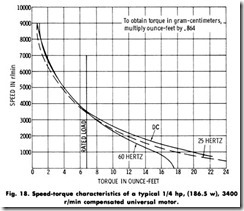
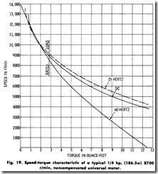
The noncompensated motor is simpler and less expensive than the compensated motor and would be used over the entire range of ratings if its performance were as good as that of the compensated motor. The noncompensated type is used for the higher speeds and lower horse power ratings only. Figs. 18 and 19 show the speed-torque curves for a compensated and noncompensated motor, respectively. It will be noted in Fig. 18 that, although the rated speed is relatively low for a universal motor, the speed-torque curves for various frequencies lie very close together up to 50% above the rated-torque load.
In Fig. 19, the performance of a much higher-speed, noncompensat ed motor is shown. For most universal-motor applications, the variation in speed at rated loads, as shown on this curve, is satisfactory. However, the speed curves separate rapidly above full load. If this motor had been designed for a lower speed, the tendency of the speed-torque curves to separate would have been more pronounced. The chief cause of the difficulty in keeping the speeds the same is the reactance voltage which exists when the motors are operated on ac. Most of this reactance voltage is produced in the field windings by the main working field. However, in the noncompensated motor, some of it is produced in the armature winding by the field produced by the armature ampere-turns. The true working voltage is obtained by sub tracting the reactance voltage vectorially from the line voltage. If the reactance is high, the performance at a given load will be the same as if there were no reactance voltage and as if the applied voltage had been reduced, with consequent reduction in speed.
SPEED CONTROL
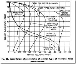
The control method used in single-phase motors depends on the type of motor selected for a certain application. Speed control is usually accomplished by means of a centrifugal switch on motors having speeds above 900 r/min. A comparison of typical speed-torque characteristics of fractional-horsepower, single-phase motors is given in Fig. 20.
Where speeds of 900 r/min and below are involved, capacitor motors utilizing voltage relays for changeover are preferable to motors using centrifugal switches, because of the sluggishness of a centrifugal switch of normal design at the lower speeds. A voltage relay for changeover is not subject to the same limitations.
Speed control, because of its more general use, has brought about the standardization of fan speeds, permitting the use of high-slip motors. A squirrel-cage motor with 8 to 10% slip and with low maximum torque operates satisfactorily, not only for constant-speed drives, but also for adjustable-speed drives through the use of voltage control on the primary winding. Within the working range of a high-slip squirrel-cage motor having adjustable voltage applied to the primary winding, the speed-torque characteristics resemble the characteristics of a wound rotor motor having different amounts of external resistance in the secondary circuit.
A tapped autotransformer connected to the motor through a multipo sition snap switch offers the simplest form of control. The transformer may have a number of taps, only two or three of which are brought out to the switch. This provides two or three speeds, any or all of which may be changed to suit the needs of the application by the proper selection of taps to connect to the switch. Additional contacts on the switch make it a complete starter and speed regulator. Two such transformers connected in open-delta for three-phase, or in each phase of a two-phase circuit, may be used to control the speed of polyphase motors. For polyphase use, the snap switch must have duplicate contacts for the transformers.
In applying speed control by means of line-voltage adjustment, it must be remembered that the speed of the drive will vary with the load. Therefore, this method of control is not suitable for centrifugal fans, especially those with damper control which affect the fan load. Two speed pole-changing motors offer a solution for centrifugal-fan drives, inasmuch as the speed on either pole combination is affected only slightly by the change in load. Motor speeds in the ratio of 2 to 1 are obtainable as 3600/1800 and 1800/900 r/min, 3 to 2 as 1800/1200 r/min; and 4 to 3 as 1200/900 r/min. Other pole combinations are possible.
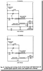
There is still another means of obtaining speed reduction on induction motors. The equivalent of building the transformer into the motor is obtained by a suitable tap on the primary winding, as shown in Fig. 21. By this means, normal speed and a single reduced speed are provided. A simple pole-changing controller is all that is required to complete the installation. Such motors are not generally available, but are provided through propeller-fan manufacturers. Each motor is designed for the characteristics of the fan it is to drive, and the tap on the winding is located to give the desired low speed.
When speed controllers are used with low-torque capacitor motors, it must be remembered that the available 50% starting torque, with full voltage applied, is reduced in proportion to the square of the voltage involved. The result is low breakaway and low accelerating torque on the low-speed setting. In manually operated control, one remedy for this Iimitation is a progressive starting switch which provides full voltage on the first (high-speed) poistion and reduced voltage on the intermediate and low-speed poistions (Fig. 22).
Where temperature control is used to start and stop the motor, a preset full-voltage starting controller is usually provided. In this case, a relay is energized by the rising voltage of the motor auxiliary winding as it accelerates the relay disconnects the motor from the direct connec tion to the line and connects it to the transformer tap for which the controller is set. In high-torque motors, this relay serves to disconnect the starting capacitor and to change over from full to reduced voltage on the motor.
Under the general subject of adjustable-speed fan motors, the ques tion of the amount of speed reduction is often debated, and although it is generally agreed that 30 to 35% speed reduction will meet almost any air-conditioning requirement, as much as 50% speed reduction is sometimes specified. In most cases, a lower percentage of speed reduction is found to be acceptable. It is fairly easy to obtain 50% reduction on a fan if the characteristic curve follows the law of horsepower load, increasing as the cube of the speed, and if the fan fully loads the motor at full speed. It is quite difficult to obtain 50% speed reduction with stability in cases where the drive is 20 to 25% overmo tored.
In considering the wide range of air-conditioning equipment, from unit heaters and coolers to barn ventilators and incubator ventilating fans, with the many types of equipment between these extremes, the foremost impression is one of economy coupled with simplicity and safety. Simplicity promotes economy. Any additional expense imposed in the interest of safety is abundantly justified from the standpoint of good operating practice. It is not advisable to use a motor of the ”long annual service” classification where the operation is infrequent, when a motor for short annual service will meet the requirements at a lower first cost with no appreciable increase in operating cost. Similarly, a frac tional-horsepower split-phase motor is less expensive than a capacitor motor.
It is essential to avoid misapplications such as low-torque motors on belted drives, or tapped-winding and transformer speed control in place of multispeed motors for centrifugal drives. The drive should always be closely motored with the correct size and type of motor to give the best results.
APPLICATION
Although single-phase motors are most commonly used in fraction al-horsepower sizes, certain applications and power-supply conditions make use of single-phase motors in integral horsepower sizes. For extremely small capacities up to 1/40 hp (18.7W), the shaded-pole type of motor is most frequently used. It provides sufficient torque for fans, blowers, and other similar equipment, and the starting current is not objectionable on lighting lines.
The split-phase motor is the most commonly used in sizes ranging from 1/30 hp (24.9 W) to 1/2 hp (373 W), particularly for fans and similar drives where the starting torque is low. In this type of motor, a built-in centrifugal switch is usually provided to disconnect the starting winding as the motor comes up to speed.
In sizes above 1/4 hp (186.5 W), a capacitor motor with 300% starting torque may be used to advantage, especially for pump and compressor drives. It may also be used in the overlapping ratings for fan drives in the lower capacities at higher speeds. However, it does not offer sufficient advantages over the split-phase motor to warrant its higher cost.
At low speeds (below 900 r/min, where centrifugal switches are less successful), and in ratings from 3/4 hp (0.5595 kW) to 3 hp (2.238 kW) at all speeds, the capacitor motor finds its widest field of application in fan drives. The running characteristics of this motor are extremely good, and the starting torque is fixed by the amount of additional capacitance added to the auxiliary motor winding during the starting period.
A low-torque capacitor motor, in which no capacitance is added to the auxiliary winding during the starting period, provides approximately 50% starting torque. This is considered sufficient for directly connected fans, if the unit is one of constant speed or is always started on the high-speed position of the starting switch. Where the fan is coupled or belted to the motor, the high-torque type of motor with the additional starting capacitance is preferable. The changeover from start to run of the high-torque type may be accomplished either through the use of a centrifugal switch, or by electrical means responsive to current decay or voltage rise as the motor approaches normal running speed.
The repulsion-induction and the repulsion-start induction motors have ratings paralleling those of the capacitor types. These motors have commutators to provide the starting torque. Under normal running conditions, the commutator of the repulsion-start, induction-run type is short-circuited, and the motor operates as an induction motor. This differs from the repulsion-induction motor in which the commutator is not short-circuited. A squirrel-cage winding deep in the rotor is inactive at starting, but takes up the load as the rotor accelerates to full speed, where the normal load is about equally divided between the repulsion and the squirrel-cage winding. The starting efficiency of both types is high, and the 300% or more starting torque that is available makes them suitable for compressor drives.
The universal-type motor, on account of its ability to run on de as well as on ac, is preferred on appliances which are required to operate on either an ac or a de circuit. Popular applications for the universal type motor are in vacuum cleaners, sewing machines, portable drills, saws, routers, home motion-picture projectors, and business machines of all kinds.
Whenever it becomes necessary to substitute a motor on any appli ance, a good deal of grief and disappointment may be avoided if a motor of the same identical size and type is reinstalled. Particular attention should be observed with respect to the nameplate data giving all the necessary information. A sound rule to follow is to copy the entire nameplate reading. This observation holds true whether it is a complete motor, or whether only a spare part is required.
