Microphone Connectors, Cables, and Phantom Power
It is almost universal practice in professional audio to provide signal sources with male connectors and signal receivers with female connectors. Additionally, it is common
practice to employ balanced circuits for both input and output in those instances where the signal levels are low and susceptible to electrical noise or cross talk interference. Indeed, many systems maintain balanced linking circuits throughout regardless of the signal levels.
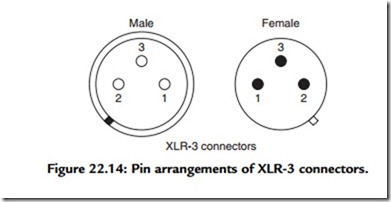
If one excludes miniature microphones that constitute a special case, the de facto standard microphone connector is the XLR-3. The male and female versions of this connector are illustrated in Figure 22.14.
Through the years the assignment of functions to the various pins has varied. The present standard assignment of the male connector at the microphone has pin 1 connected to the microphone case. Pin 2 is connected to the microphone circuitry such that a positive pressure on the microphone diaphragm drives the voltage at pin 2 in the positive sense. Pin 3 is connected to the microphone circuitry such that a positive pressure on the microphone diaphragm drives the voltage at pin 3 in the negative sense. Pins 2 and 3 are balanced with respect to pin 1.
Quality microphone cables consist of a twisted pair of insulated, color-coded inner conductors formed from stranded copper wire covered by a tightly woven copper braided shield with the combination encased in an insulating jacket. The conductors may be tinned, although this is not always the case. The cable is fitted with a female connector at one end and a male connector at the other. The connector pin assignments in this instance have pin 1 connected to the shield with the option of also strapping the connector shell to pin 1. Pin 2 is connected to the positive signal conductor while pin 3 is connected to the negative signal conductor. Microphone cable is also often used as the connecting cable in link circuits between mixers, subsequent signal processing units, and power amplifiers.
Shielded, twisted pairs in balanced circuits are an absolute necessity in handling low- level signals in order to avoid electromagnetic interference. The braided shield alone offers protection from electrostatic fields but offers very little protection from changing magnetic fields. The practice of employing twisted pair conductors stems from experience gleaned from the early days of the telephone industry.
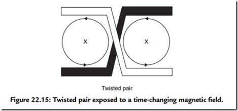
In former times, long distance circuits between cities and local circuits in rural areas employed open bare wire pairs affixed to separate glass insulators attached to multiple cross arms, which were in turn elevated by poles. It was learned early on that open-air electrical power lines that often followed parallel paths caused interference. It was found that by periodically transposing the positions occupied by the two conductors of a given circuit pair, that the interference could be reduced greatly if not eliminated altogether. This transposition amounted to periodically twisting without touching one conductor of a circuit pair over the other, in effect forming an insulated, twisted pair even though the distance between twists was relatively large. The explanation for this annulment of the interference appears in Figure 22.15.
In Figure 22.15 imagine that the twisted pair of conductors is replicated to the right as well as to the left to form an extended circuit. Imagine also that in the vicinity a magnetic field is instantaneously directed into the figure as indicated by the X’s and that the field strength is increasing with time. Examine the two closed paths as indicated by the circles. According to Lenz’s law, the induced voltage acting in the loops has the sense indicated by the arrows. Now look at the white conductor in the upper left, the induced voltage in this portion of conductor is in the same direction as is the arrow adjacent to it. Compare
that with the induced voltage in the white conductor in the lower right in which the induced voltage is oppositely directed.
The same analysis applied to the two similar segments of the black conductor yields identical results. There is no voltage induced in either conductor in the transposition region as the arrows in the adjacent circles are oppositely directed. In practice, the magnetic field alternates but as it changes its direction of growth, the induction in the loops reverses direction also while the net voltage induced in the transposed conductors remains at zero. Static magnetic fields are of no consequence unless a conductor is moving through them. Even so, a twisted pair translated through a magnetic field that is static in time will experience a net-induced voltage only if the magnetic field varies rapidly with position in space.
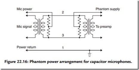
Air capacitor microphones require a source of polarization voltage, as well as a DC power source for operating the source follower that handles the microphone signal. Electret capacitor microphones are self-polarized but still require power for the source follower signal circuitry. This power is usually supplied by the microphone mixer via the cable connecting the microphone to the mixer. The circuitry employed for accomplishing this must maintain balance of the microphone signal circuitry. DC circuits that perform this task are called phantom power supplies. One such arrangement is depicted in Figure 22.16.
The arrangement of Figure 22.16 features an output transformer internal to the microphone housing, as well as an input transformer internal to the mixer. The DC voltage is applied equally to the microphone signal conductors at pins 2 and 3. The DC
return circuit is through the shield on the microphone cable at pin 1. Conductors 2 and 3 have the same DC potential and hence there is no direct current in the transformer windings. In order to accomplish this, the resistors denoted as R must be carefully
matched to be equal to within ±0.1%. This precision is required not only for DC balance but also to maintain a large common mode rejection ratio. Commonly encountered voltage and resistor values are listed here.
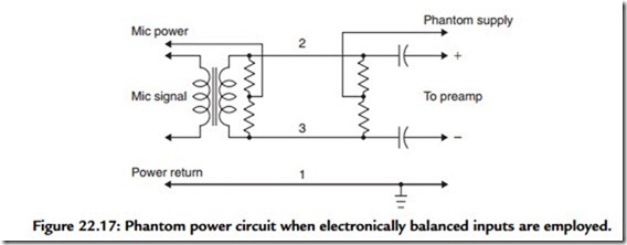
There is a trend by some designers to employ electronically balanced inputs in the mixer input microphone circuitry. In such instances, blocking capacitors must be employed to isolate the differential mixer input from DC while maintaining continuity for the microphone signal. Such an arrangement appears in Figure 22.17.
The phantom power circuits of Figures 22.16 and 22.17 work well but both have an undesirable feature. The necessity of the employment of matched balancing resistors in both instances limits the current that may be supplied to power the microphone circuitry. This limitation can be removed through the employment of transformers that are center tapped on the appropriate windings. Such transformers would be quite expensive because of the necessity of very accurately having both an equal number of turns on either side
of the center tap as well as exact resistance of the turns on either side of the center tap. If this is not accomplished, direct current will exist in the transformer winding and the signal circuit will no longer be exactly balanced.
Finally, a word of caution is in order. Sound systems may employ just a few or a very large number of microphone cables not only for microphones but also for link circuits. It is important to maintain correct signal polarity in all microphones, microphone cables, link circuits, processing electronics, loudspeaker wiring, and loudspeakers. There are convenient commercial devices called polarity checkers that can be employed to check individual microphones, cables, and overall system polarity. An investment in such devices is modest, time saving, and will earn its keep many times over.


