Hall Generator Applications
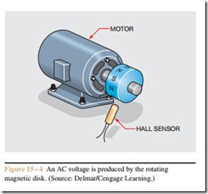
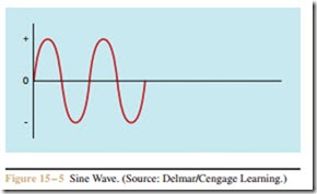
The Hall generator can be used to measure the speed of a rotating device. If a disk with magnetic poles around its circumference is attached to a rotating shaft, and a Hall sensor is mounted near the disk, a voltage will be produced when the shaft turns. Since the disk has alternate magnetic polarities around its circumference, the sensor will pro- duce an AC voltage. Figure 15 – 4 shows a Hall generator used in this manner. Figure 15 – 5 shows the AC waveform produced by the rotating disk. The frequency of the AC voltage is proportional to the number of magnetic poles on the disk and the speed of rotation.
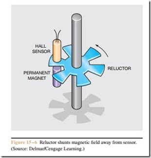
Another method for sensing speed is to use a reluctor. A reluctor is a ferrous metal disk used to shunt a magnetic field away from some other object. This type of sensor uses a notched metal disk attached to a rotating shaft. The disk separates a Hall sensor and a permanent magnet (Figure 15 – 6). When the notch is between the sensor and the magnet, a voltage is produced by the Hall generator. When the solid metal part of the disk is be- tween the sensor and magnet, the magnetic field is shunted away from the sensor. This causes a significant drop in the voltage produced by the Hall generator.
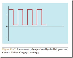
Since the polarity of the magnetic field does not change, the voltage produced by the Hall generator is pulsating direct current instead of alternating current. Figure 15 – 7 shows the DC pulses produced by the
generator. The number of pulses produced per second is proportional to the number of notches on the reluctor and the speed of the rotating shaft.
Position Sensor
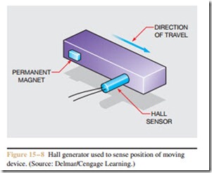
The Hall generator can be used in a manner similar to a limit switch. If the sensor is mounted beside a piece of moving equipment, and a permanent magnet is at- tached to the moving equipment, a voltage will be pro- duced when the magnet moves near the sensor (Fig- ure 15 – 8). The advantages of the Hall sensor are that it has no lever arm or contacts to wear like a common limit switch, so it can operate through millions of operations of the machine.
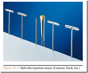
A Hall effect position sensor is shown in Fig- ure 15 – 9. Notice that this type of sensor varies in size
and style to fit almost any application. Position sensors operate as digital devices in that they sense the presence or absence of a magnetic field. They do not have the ability to sense the intensity of the field.
Hall Effect Limit Switches
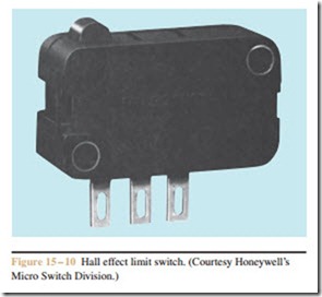
Another Hall effect device used in a very similar appli- cation is the Hall effect limit switch (Figure 15 – 10). This limit switch uses a Hall generator instead of a set of con- tacts. A magnetic plunger is mechanically activated by the small button. Different types of levers can be fitted to the switch, which permits it to be used for many applications.
These switches are generally intended to be operated by a 5 volt DC supply for TTL (Transistor-Transistor Logic) applications, or by a 6 to 24 volt DC supply for interface with other types of electronic controls or to provide input for programmable controllers.
Current Sensor
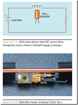
Since the current source for the Hall generator is provided by a separate power supply, the magnetic field does not have to be moving or changing to produce an output voltage. If a Hall sensor is mounted near a coil of wire, a voltage will be produced by the generator when current flows through the wire. Figure 15 – 11 shows a Hall sensor used to detect when a DC current flows through a circuit. A Hall effect sensor is shown in Figure 15 – 12.
The Hall generator is being used more and more in industrial applications. Since the signal rise and fall time of the Hall generator is generally less than 10 microseconds, it can operate at pulse rates as high
as 100,000 pulses per second. This makes it especially useful in industry.
Linear Transducers
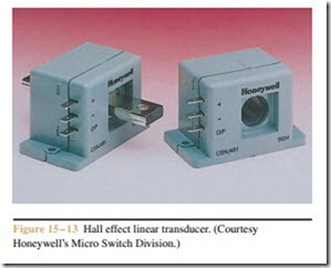
Linear transducers are designed to produce an output voltage that is proportional to the strength of a magnetic field. Input voltage is typically 8 to 16 volts, but the amount of output voltage is determined by the type of transducer used. Hall effect linear transducers can be obtained that have two types of outputs. One type has a regulated output and produces voltages of 1.5 to 4.5 volts. The other type has a ratiometric output and produces an output voltage that is 25% to 75% of the input voltage. A Hall effect linear transducer is shown in Figure 15 – 13.
Review Questions
1. What material was used to make the first Hall generator?
2. What two factors determine the polarity of the output voltage produced by the Hall generator?
3. What two factors determine the amount of voltage produced by the Hall generator?
4. What is a reluctor?
5. Why does a magnetic field not have to be moving or changing to produce an output voltage in the Hall generator?
Related posts:
Incoming search terms:
- hall effect generator
- what is hall generator
- operation of hall effect pulse generator
- Describe the working of a hall effect generator
- use of hall effect generator
- operation hall effect pulse generator
- most used in hall effect pulse generator
- hall genrator
- hall generators
- hall generator
- hall effect sensor applications for AC generator
- hall effect sensor
- hall effect on generators
- where to find hall effect sensor
