Frequency Control
Frequency control operates on the principle that the frequency of the induced voltage in the motor secondary (rotor) will decrease as the speed of the rotor in- creases. The rotor windings contain the same number of poles as the stator. When the motor is stopped and
power is first applied to the stator windings, the voltage induced into the rotor will have the same frequency as the power line. This will be 60 hertz throughout the United States and Canada. When the rotor begins to turn, there is less cutting action between the rotating magnetic field of the stator and the windings in the rotor. This causes a decrease in both induced voltage and frequency. The greater the rotor speed becomes, the lower the frequency and amount of the induced voltage. The difference between rotor speed and synchronous speed (speed of the rotating magnetic field) is called slip and is measured as a percentage. Assume that the stator winding of a motor has four poles per phase. This would result in a synchronous speed of 1800 rpm when connected to 60 hertz. Now assume that the rotor is turning as a speed of 1710 rpm. This is a difference of 90 rpm. This results in a 5% slip for the motor.
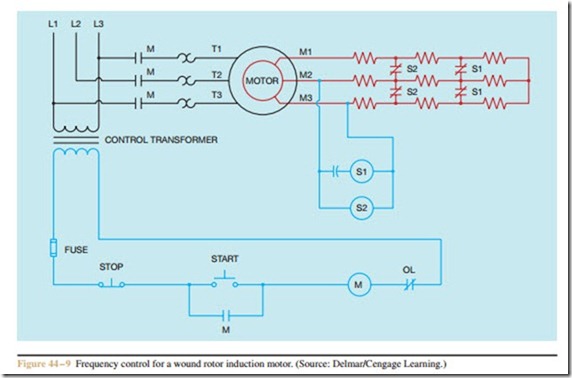
A diagram of a wound rotor motor starter using frequency relays is shown in Figure 44 – 9. Note that the frequency relays are connected to the secondary winding of the motor and that the load contacts are connected normally closed instead of normally open. Also note that a capacitor is connected in series with one of the frequency relays. In an alternating current circuit, the current limiting effect of a capacitor is called capacitive reactance. Capacitive reactance is inversely proportional to the frequency. A decrease in frequency causes a corresponding increase in capacitive reactance.
When the START button is pressed, M contactor energizes and connects the stator winding to the line. This causes a voltage to be induced into the rotor circuit at a frequency of 60 hertz. The 60 hertz frequency causes both S1 and S2 contactors to energize and open their load contacts. The rotor is now connected to maximum resistance and starts in the lowest speed. As the frequency decreases, capacitive reactance increases, causing contactor S1 to de-energize first and re-close the S1 contacts. The motor now increases in speed, causing a further reduction of both induced voltage and frequency. When contactor S2 de-energizes, the S2 load contacts re-close and short out the second bank of resistors. The motor is now operating at its highest speed.
The main disadvantage of frequency control is that some amount of resistance must remain in the circuit at all times. The load contacts of the frequency relays are closed when power is first applied to the motor. If a set of closed contacts were connected directly across the M leads, no voltage would be generated to operate the coils of the frequency relays and they would never be able to open their normally closed contacts.
Frequency control does have an advantage over other types of control in that it is very responsive to changes in motor load. If the motor is connected to a light load, the rotor will gain speed rapidly, causing the motor to accelerate rapidly. If the load is heavy, the rotor will gain speed at a slower rate, causing a more gradual increase in speed to help the motor overcome the inertia of the load.
Review Questions
1. How many slip rings are on the rotor shaft of a wound rotor motor?
2. What is the purpose of the slip rings located on the rotor shaft of a wound rotor motor?
3. A wound rotor induction motor has a stator that contains six poles per phase. How many poles per phase are in the rotor circuit?
4. Name three factors that determine the amount of torque developed by a wound rotor induction motor.
5. Explain why the wound rotor motor produces the greatest amount of starting torque per ampere of starting current of any three-phase motor.
6. Explain why controlling the rotor current controls the stator current also.
7. What is the function of a micro limit switch when used with a manual controller for a wound rotor motor?
8. Why are the resistors used in the rotor circuit smaller for a starter than for a controller?
9. What is rotor slip?
10. A wound rotor has a synchronous speed of 1200 RPM. The rotor is rotating at a speed of
1075 RPM. What is the percent of rotor slip and what is the frequency of the induced rotor voltage?
11. Refer to the circuit shown in Figure 44 – 6. Assume that the motor is running at full speed and the STOP button is pressed. The motor stops running. When the manual control knob is returned to the highest resistance setting, the motor immediately starts running in its lowest speed. Which of the following could cause this problem?
a. The STOP push-button is shorted.
b. The START push-button is shorted.
c. M auxiliary contact is shorted.
d. The micro limit switch contact did not re-close when the control was returned to the highest resistance setting.
12. Refer to the circuit shown in Figure 44 – 7. Assume that the timers are set for a delay of 3 seconds each. When the START button is pressed, the motor starts in its lowest speed. After 3 seconds, the motor accelerates to second speed, but never reaches third speed. Which of the following cannot cause this problem?
a. TR1 timer coil is open.
b. S1 contactor coil is open.
c. TR2 timer coil is open.
d. S2 contactor coil is open.
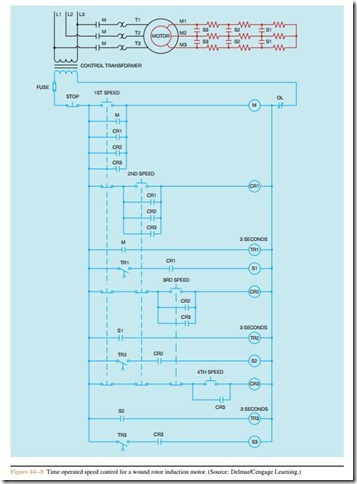
13. Refer to the schematic diagram in Figure 44 – 8.
Assume that the motor is not running. When the 3RD SPEED push-button is pressed, the motor starts in its lowest speed. After a delay of 3 seconds, the motor accelerates to second speed and 3 seconds later to 3 speed. After a period of about 1 minute, the 4TH SPEED push-button is pressed, but the motor does not accelerate to fourth speed. Which of the following could cause this problem?
a. Control relay CR2 coil is open.
b. S2 contactor coil is open.
c. CR3 coil is shorted.
d. S2 contactor coil is open.

