VALVE INSPECTION
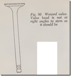
After the valves have been cleaned they should be inspected carefully for defects. Excessive heat may cause the valve to bend or warp, Fig. 80. Such a valve should be discarded.
Examine both the upper and lower sides of the head for cracks. If even a small crack is found, scrap the valve.
Inspect the face of each exhaust valve for burn ing. Even if only a small burned spot is found the valve should be scrapped because the metal ad jacent to the spot has probably been damaged and further trouble can be expected if such a valve is used again. The appearance of a burned valve is readily recognized. It looks like a poker which has remained too long in a hot fire. A burned valve, however, should not be confused with a pitted valve. Pits are caused by slight corrosion resulting from hot exhaust gases sweeping past the face of the valve and gouging out shallow depressions which are then partially filled with carbon. Such a valve is readily refinished so that it is as good as new.
If the valve stem is noticeably corroded the valve should be discarded.
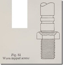
If the tip of the valve stem is scratched it should be smoothed up with a valve refacing tool. If the top face of the tappet adjusting screw, Fig. 81, has a depression worn in it (caused by loose valve stem guide, loose tappet guide or both) a new adjusting screw should be installed or the old screw should be smoothed up in a valve refacing tool.
Both the valve stem and its guide should be checked for wear. Valve stem and guide wear at the top is caused by off-center seating of the valve. Wear of stem and guide at the bottom is caused by too much clearance between the valve tappet and its guide.
Valve Stem-to-Guide Clearance
The exact stem-to-guide clearance varies con siderably in diff rent makes of engines. Usually, greater clearance is specified for the exhaust valve than for the intake by the engine manufacturer because the exhaust runs much hotter and there fore expands more.
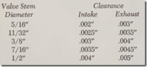
The valve stem-to-guide clearances recommended by a leading valve manufacturer are as follows:
If the clearance is more than .002″ greater than given above, new valves and guides should be installed. On engines without removable valve guides, valves with overside stems should be in stalled and the valve guides reamed to provide the specified clearance.
Reaming Valve Guides
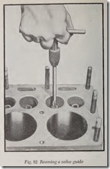
After installing new guides, or if valves with oversize stems are to be installed, the new guides or guide holes should be reamed. Lubricate the reamer blades with light oil. Insert the reamer in the valve guide, Fig. 82, and turn it slowly clock wise while pressing down gently. On L-head en gines, place a rag underneath the valve guide to prevent metal cuttings falling into the crankcase.
When reaming is completed, remove the reamer by continuing to turn it clockwise while lifting it out of the hole. Never turn a reamer in the oppo site direction as it will damage the cutting blades .
Non-adjustable reamers are ma de for some popular makes of engines, tl1e reamer being the correct diameter for a given standar d size or over size valve stem.
Measuring Valve Stem-to-Gu ide Clearance
The stem-to-guide clearance may be measured in four ways: with a micrometer; with a dial gauge; with 1/16″ wide shim stock; with Go and No-Go gauges. The surfaces should be perfectly clean before any measurements are made.
After measuring the clearance and it is found to be excessive, install a new valve. If this does not reduce the clearance appreciably, install a new guide. If the engine is one which has no remov able valve guides, ream the guide h ole to accom modate the next oversize valve.
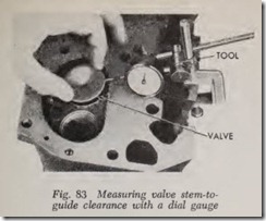
When using a dial gauge to measure valve-to guide clearance, install a suitable sleeve over th e valve stem to hold the valve at working height in the head or block. Attach a dial indicator having a stem at right angle with the edge of the valve, Fig.83. Move the valve to and from the gauge. If the clearance is more than it should be install a new valve and guide.
The Go and No-Go type plug gauges are quite popular because of the facility with which guides can be checked. However, there are two undesir able guide conditions which are difficult to check with gauges of this type: elliptical or egg-shaped bore wear, and bell-mouthing at the port end of the guide. Careful guide inspection will detect egg-shaped wear, and the careful use of the No Go gauge will tend to show the degree of bell mouthing.
Measure the diameter of the valve stem with a micrometer and write down the reading. Then measure the diameter of the valve guide with an inside caliper and write down the reading. Sub tract the former reading from th e latter in order to determine the clearance. If the clearance is more than it should be a new valve and/or guide should be installed.
Stem-to-guide clearance may be checked with a 1/16″ wide shim stock which is available in various thicknesses. Insert a strip of the shim stock in the guide and then insert the valve stem. By trial and error, select a thickness of shim stock which pro vides a very slight drag when the valve is moved up and down in the guide. If, for example, a piece of shim stock .003″ thick provides a slight drag, then the stem-to-guide clearance is .003″.
VALVE GUIDE, REPLACE
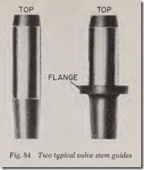
The method to use in removing and replacing a valve guide depends on its construction. The most common type is shown at left in Fig. 84. It is pressed into the guide hole and held in position by friction. The guide shown in the right view, Fig. 84, is used on a few of the older engines. Its flange is intended to fit snugly against the roof of the valve chamber on L-head engines or on top of the cylinder head on overhead valve engines. The flanged valve guide must be removed and re placed from below on L-head engines.
On overhead valve engines the straight valve guide can be removed from either the top or bottom of the head, whichever is more convenient.
If it is desirable to remove L-head valve guides by driving them downward, the valve lifters may interfere unless they can be removed. Barrel type lifters are readily lifted out after the valves and springs are removed but mushroom type lifters cannot be taken out without removing the cam shaft unless the lifter guides operate in removable guide brackets.
Therefore, if the engine is equipped with mush room type lifters and the lifter guides are not removable , there are three possibilities: ( 1) There may be room enough to drive the guide down ward and out after removing the lifter adjusting screw. ( 2) With a suitable puller the guide may be pulled upward and out. ( 3) If a puller is not available, drive the guid e downward almost to the point where it contacts the lifter screw. Cut a sharp nick in the guide with a chisel near the “roof’ of the valve chamber and then break the protruding portion of th e guide off with a ham m er. The remaining portion of the guide in the guid e hole can then be driven down and out.
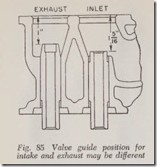
Before removing a guide, measure the distance it sticks out into the valve port with a steel scale and record this figure. Note that the distance may be different for intake and exhaust guides, Fig. 85.
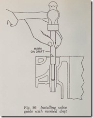
Instead of measuring the distance, insert a drift in the guide, Fig. 86, and IJlark the drift at the top of the block. When the new guide is installed, drive in to this mark.
If the guide has a flange, Fig. 84, it is not neces sary to make this measurement because the flange automatically positions the guide.
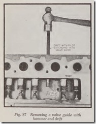
Fig. 87 shows how a valve guide is driven out with a drift and hammer. The drift has a pilot on its lower end which should be the same diameter as the valve stem.
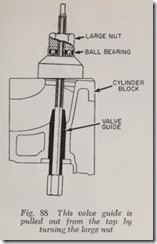
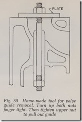
If the valve lifters interfere with valve guide removal, the guides may be pulled out from the top. Fig. 88 shows one type of puller; another puller is shown in Fig. 89.
To install a valve guide, first lubricate its outer surface with engine oil. It may be installed with a hammer and drift, Fig. 87. The pilot on the drift should fit the valve guide hole in order to align the guide while it is being hammered into place. Center the guide in the hole and tap the drift gently until the guide is firmly entered in the hole. The force of the hammer blows can then be in creased somewhat. Be careful not to drive the guide in too far. If by accident the guide is driven in too far, it may be brought back to its correct position on L-head engines by the use of a puller. On overhead valve engines, the guide can be driven back by turning the head over and using a drift.
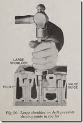
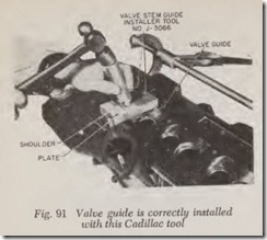
To insure that the guide is driven in just the right distance, special tools are made for given engines. Fig. 90 shows such a tool with a large shoulder which butts against the block when the valve guide is driven in far enough. Fig. 91 illus trates a tool for Cadillac engines. When the shoulder on the drift handle contacts the plate, the guide is correctly positioned.
Check the clearance between the new guides and valves, and ream the guides if the clearance is too little. Light reaming may also be required if the guides have been slightly distorted during installation.
